Remote I/O Adapter Module 15
Publication 1747-IN014C-EN-P - January 2003
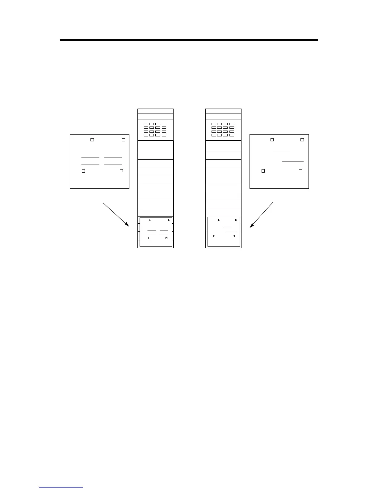
Installing I/O Module Addressing Labels
Attach the Remote PLC or Remote SLC label to the outside bottom of each I/O
module in your 1747-ASB chassis, as shown below. Fill out each label completely.
Using a SLC as a Master
If you are using a SLC processor as a master, each I/O module is addressed by the
physical slot number of the 1747-SN scanner and the word that the I/O module
uses in the scanner image. Data is transferred on the network by logical rack and
logical group number. Refer to Remote I/O Scanner User Manual, publication
number 1747-6.6, for more information on the 1747-SN.
Using a PLC as a Master
If you are using a PLC processor as a master, each I/O module is addressed by
logical rack and logical group, regardless of what physical slot it is in. If using a
PLC processor as a master, attach octal labels.
BT Discrete
0 - 7 8 - 15
SN Slot
SN Word(s)
Remote SLC System
Rack Group(s)
BT
Discrete
0 - 7 10 - 17 0 - 7 8 - 15
SN Slot
SN Word(s)
INPUT INPUT
Remote PLC System
BT
Discrete
Remote SLC System
I:
O:
Rack Group(s)
Discrete
0 - 7 10 - 17
I:
O:
Remote PLC
System
BT
Remote SLC Label
Remote PLC® Label

 Loading...


