6 Remote I/O Adapter Module
Publication 1747-IN014C-EN-P - January 2003
For more information on addressing, refer to the Remote I/O Adapter Module User
Manual, publication number 1747-6.13.
Configuring the Module
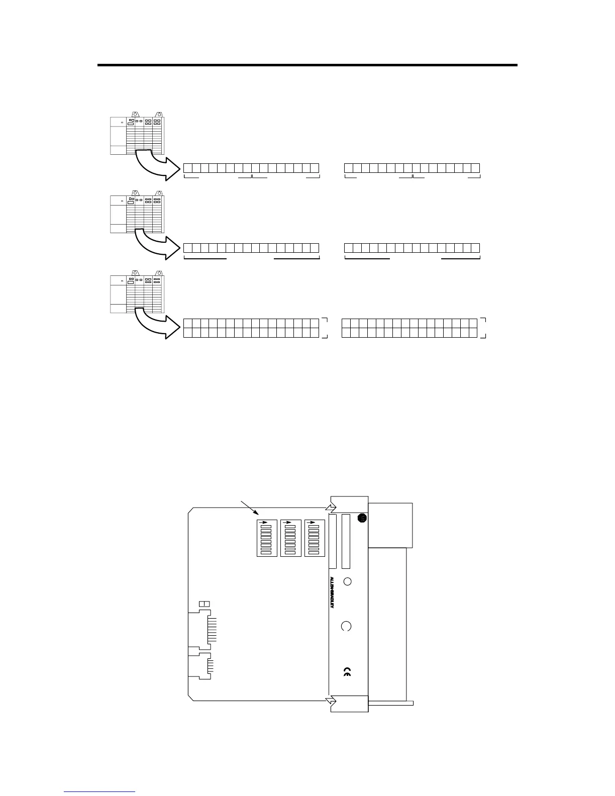
The 1747-ASB module parameters are configured by three DIP switches, shown
below.
2-Slot
Addressing
Input Image Output Image
Two slots are addressed as one logical group.
1-Slot
Addressing
Input Image Output Image
One slot is addressed as one logical group.
1/2-Slot
Addressing
Input Image
Output Image
One slot is addressed as two logical groups.
Slot Slot
Slot Slot
Slot
Slot
Slot Slot
SLC 500
CAT SER
SERIAL NO. FRN
U
L
SA
1 2 3 45678
SW1
O
N
1 2 3 45678
SW2
O
N
1 2 3 45678
SW3
O
N
IMPORTANT :
INST ALL IN SLOT ZERO OF MODULAR CHASSIS ONLY
REMOTE I/O ADAPTER MODULE
F AC 1M MADE IN USA
CURRENT REQUIREMENT : 375mA
LISTED IND. CONT . EQ.
FOR HAZ. LOC. A196
CLASS 1, GROUPS A, B, C AND D, DIV . 2
OPERATING
TEMPERATURE
CODE T3C
DIP Switches

 Loading...


