Publication 1794-UM063A-EN-P - March 2006
Install Your FLEX I/O Analog Modules 3-7
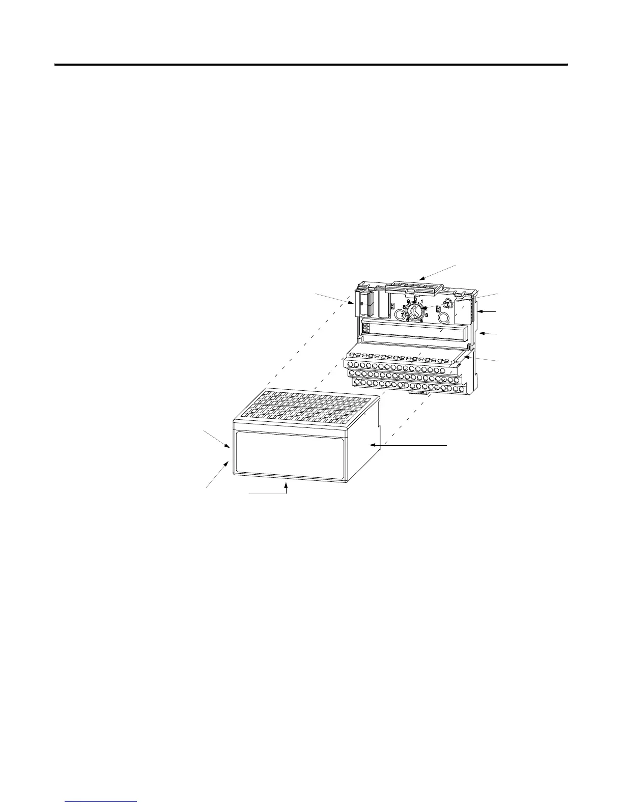
Mount the Analog Modules on the Terminal Base Unit
The HART analog input and output modules mounts on a 1794-TB3g or
1794-TB3GS terminal base unit.
1. Rotate keyswitch (1) on terminal base unit (2) clockwise to position 3 for
the 1794-IE8H or position 4 for the 1794-OE8H as required for each
type of module.
Do not change the position of the keyswitch after wiring the
terminal base unit.
2. Make certain the flexbus connector (3) is pushed all the way to the left
to connect with the neighboring terminal base/adapter.
You cannot install the module unless the connector is fully
extended.
3. Make sure the pins on the bottom of the module are straight so they will
align properly with the connector in the terminal base unit.
4. Position the module (4) with its alignment bar (5) aligned with the
groove (6) on the terminal base.
5. Press firmly and evenly to seat the module in the terminal base unit.
The module is seated when the latching mechanism (7) is locked into
the module.
6. Remove cap plug (8) and attach another terminal base unit to the right
of this terminal base unit if required.
1
7
8
2
6
3
4
5
40231
Label Under Here
or Under Here

 Loading...


