Publication 1794-UM063A-EN-P - March 2006
3-12 Install Your FLEX I/O Analog Modules
5. If continuing power to the next terminal base unit, connect a jumper
from terminal 50 (+V dc) on this base unit to +V dc power terminal on
the next terminal base unit.
6. If continuing common to the next terminal base unit, connect a jumper
from terminal 51 (-V common) on this base unit to the -V common
terminal on the next terminal base unit.
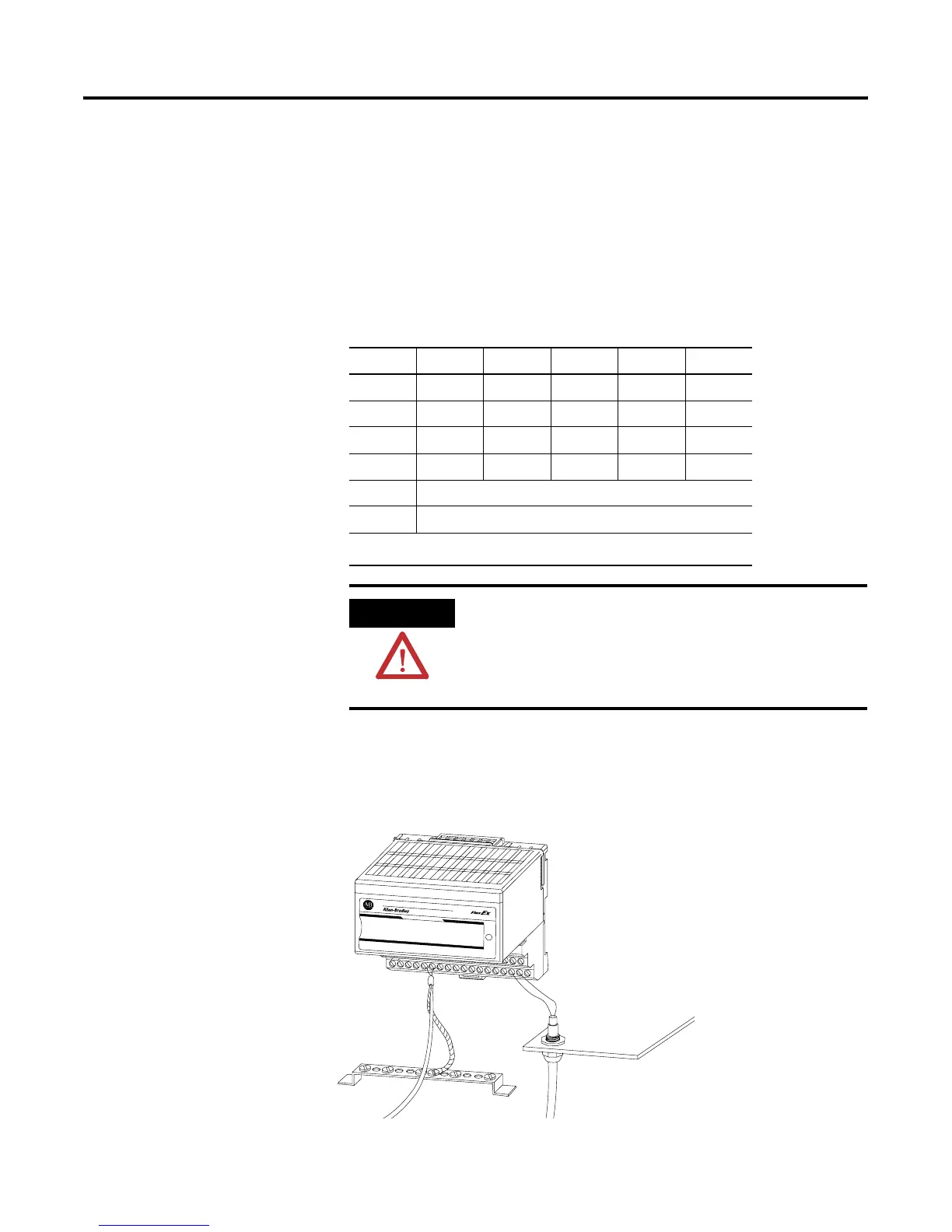
Ground the Module
All I/O wiring must use shielded wire. Shields must be terminated external to
the module, such as bus bars and shield-terminating feed throughs.
Table 3.3 Wiring connections for the 1794-OE8H Module
Output Output + Output – Output Output + Output –
Output 0 A-0 A-1 Output 4 B-17 B-18
Output 1 A-4 A-5 Output 5 B-21 B-22
Output 2 A-8 A-9 Output 6 B-25 B-26
Output 3 A-12 A-13 Output 7 B-29 B-30
+V Terminals 34 and 50
-V Terminals 35 and 51
Terminals 16, 33, 40, 41, 42, 43, 44, and 45 are connected to chassis ground.
ATTENTIONATTENTION
Do not use the unused terminals on the terminal base unit.
Using these terminals as supporting terminals can result in
damage to the module and/or unintended operation of your
system.
30820

 Loading...


