1 Publication 1794-UM063A-EN-P - March 2006
Chapter
6
Troubleshoot the FLEX I/O
Analog I/O Modules
What This Chapter Contains
Read this chapter to troubleshoot your I/O module.
Status Indicators
1794-IE8H Module
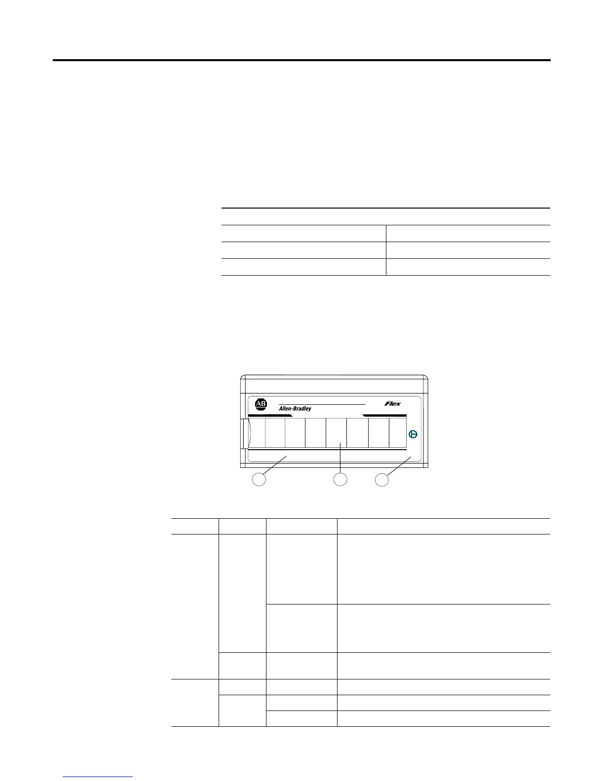
The 1794-IE8H module has one power indicator that is on when power is
applied to the module and one status indicator for each input.
For Information On See Page
Status Indicators 6-1
Repair 6-2
Chapter Summary 6-2
Table 6.1 1794-IE8H Status Indicators
Indicator Color State Meaning
Status Red On At power up – Channel 0 indicator lights at powerup until
all internal diagnostics are checked. After successful
powerup, the indicator goes off if no fault is present.
After successful powerup – Indicates a critical fault
(diagnostic failure, etc.)
Blinking (when
faults are
enabled, and bit
set)
Indicates a noncritical channel fault
Yellow On/blinking HART device was found on the associated channel (when
configured)
Power — Off Module not powered
Green On Module receiving power
Blinking No flexbus communication
A = Status indicators
B = Insertable labels for writing individual input
designations
C = Power indicator
PWR
1794-IE8H
8 CH HART ANALOG INPUT
IN1IN0 IN2 IN3 IN4
IN5
IN6 IN7
3
A
B
C
I/O

 Loading...


