Publication 1794-UM063A-EN-P - March 2006
3-8 Install Your FLEX I/O Analog Modules
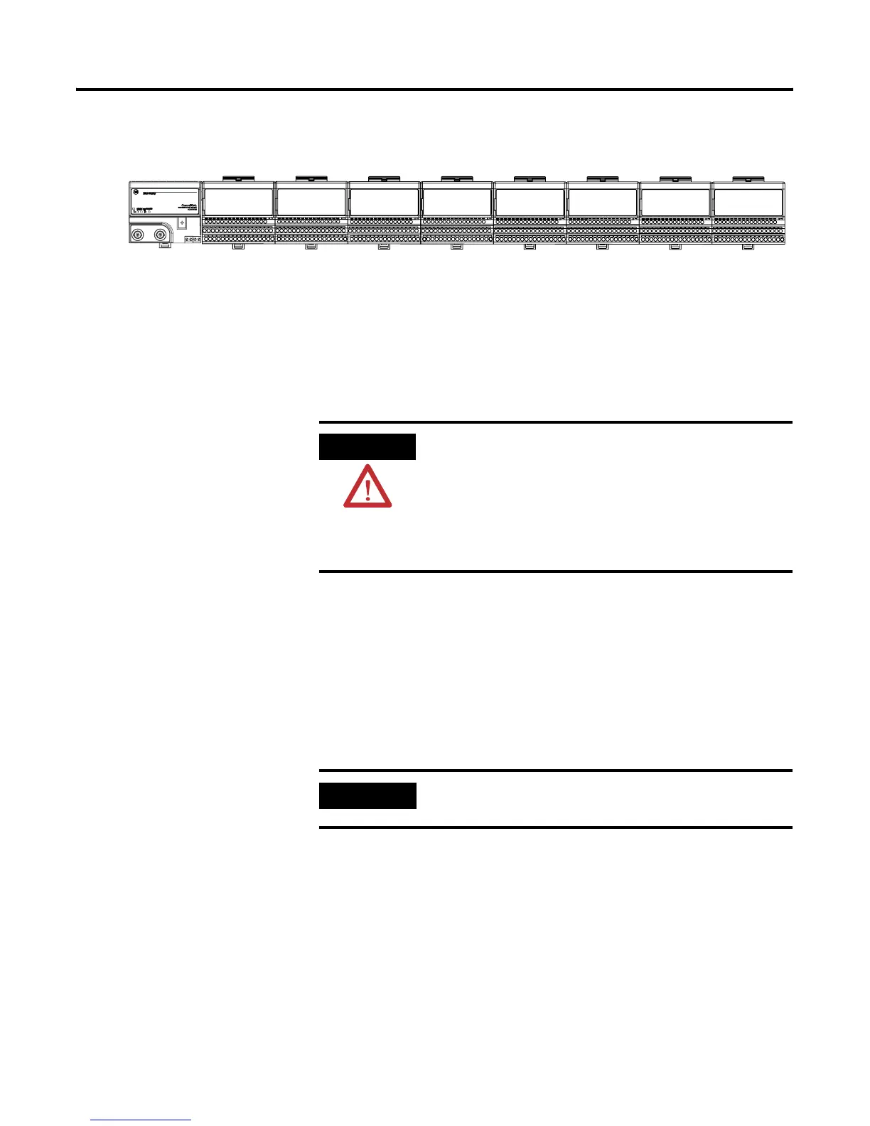
Make sure the last terminal base has the cap plug (8) in place.
The adapter is capable of addressing eight modules. Do not exceed a maximum of
eight terminal base units in your system.
Wire the Terminal Base
Units
Wiring the FLEX I/O HART analog input modules is done using the
1794-TB3G or the 1794-TB3GS terminal base unit..
Connect Wiring to the
FLEX I/O HART Analog
Modules
Inputs/Outputs
Each 1794-IE8H input can be operated from an analog field device signal, and
each 1794-OE8H output channel can operate an analog field device.
The channels of the 1794-IE8H are electrically connected to each other and
have a common plus-line. The channels of the 1794-OE8H are electrically
connected to each other.
41307
ATTENTIONATTENTION
The FLEX I/O analog modules do not receive primary
operational power from the backplane. +24V dc power must be
applied to your module before operation. If power is not
applied, the module position will appear to the adapter as an
empty slot in your chassis. If the adapter does not recognize
your module after installation is completed, cycle power to the
adapter.
IMPORTANT
When interconnecting several lines, you must consider the total
accumulated power.

 Loading...


