EasyManuals Logo

Allen-Bradley CENTERLINE User Manual

Allen-Bradley CENTERLINE
88 pages
To Next Page IconTo Next Page
To Previous Page IconTo Previous Page
Page #51 background imageLoading...
Page #51 background image
Publication 2100-IN012B-EN-P - April 2005
Installing and Removing Plug-In Units 5-3
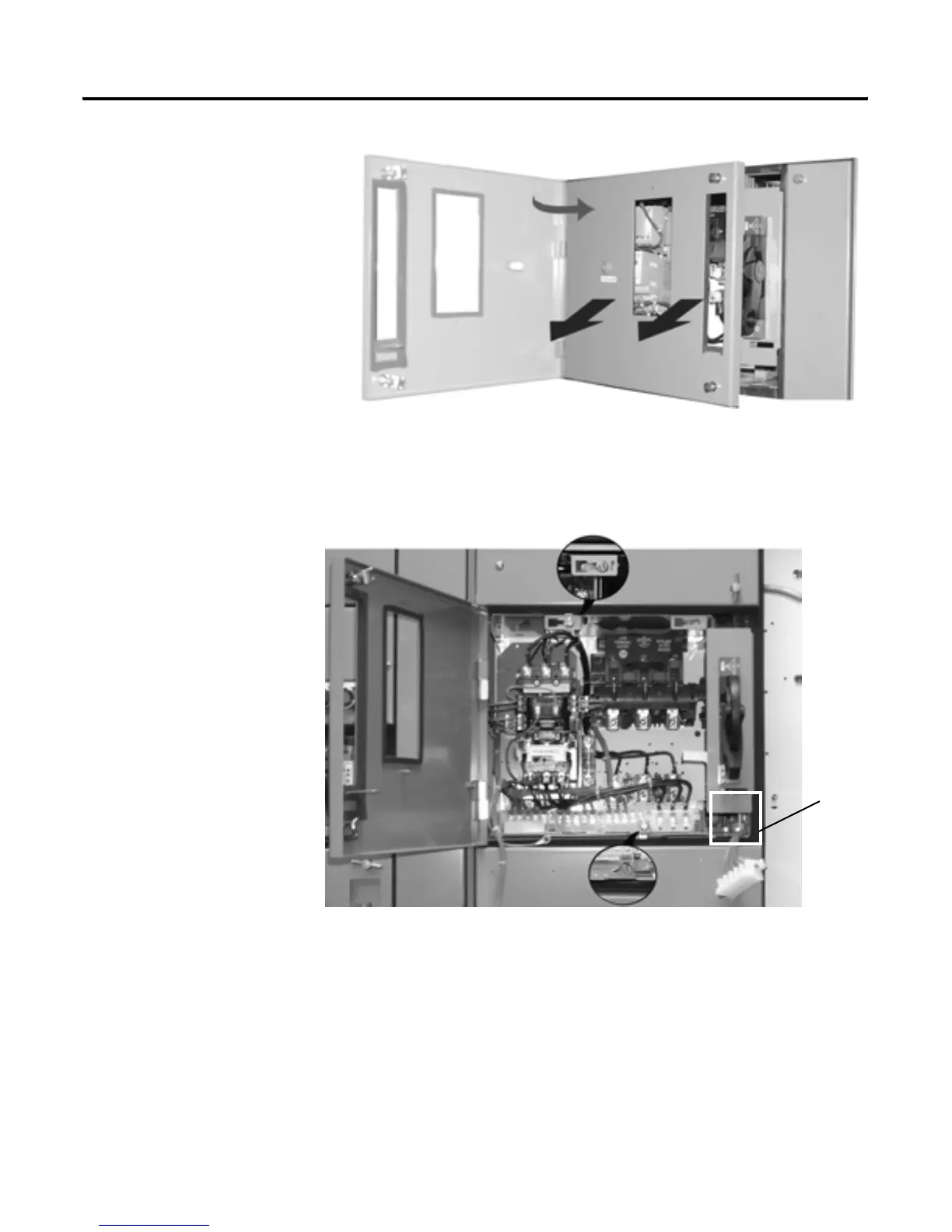
Figure 5-3 Removing the Unit Door
1. Swing door to near closed position.
2. Lift door outward to remove.
Figure 5-4 Disengage the Captive Latches
1. Disengage captive latches located at front of unit, one at top and one at
bottom of the unit. Units that are 2.0 space factor and larger have two
latches at top.
2. Detach front portion of pull-apart terminal blocks from the unit base.
Place wires/terminal blocks in line with wiring clearance tunnel.
3. Remove other cables or devices that would prevent unit withdrawal.
Wiring
Tunnel

Table of Contents

Questions and Answers:

Question and Answer IconNeed help?

Do you have a question about the Allen-Bradley CENTERLINE and is the answer not in the manual?

Allen-Bradley CENTERLINE Specifications

General IconGeneral
Short Circuit Current Rating (SCCR)Up to 100kA
Modular DesignYes
TypeMotor Control Center (MCC)
VoltageUp to 600V AC
Communication ProtocolsEtherNet/IP, DeviceNet
Enclosure TypeNEMA 1, NEMA 3R, NEMA 4, NEMA 4X, NEMA 12
Standards ComplianceUL 845, IEC 61439

Related product manuals