111 Publication 1756-UM001G-EN-P - January 2007
Chapter
9
Configure Redundancy
Introduction
This chapter explains how the ControlLogix redundancy system uses
an identical pair of ControlLogix chassis to keep your machine or
process running if a problem occurs with any equipment in a
redundant chassis.
Additional Resources
For additional information consult the ControlLogix Redundancy
System User Manua, publication 1756-UM523.
ControlLogix Redundancy
Overview
Redundancy provides for higher system availability by switching
control to a secondary controller chassis if anything in the primary
controller chassis fails. The redundant system switches from primary
to secondary due to:
• power loss to primary chassis.
• hardware or firmware failure of any module in the primary
chassis.
• a major fault in the user program on the primary controller.
• disconnection of a ControlNet tap or ControlNet cable to a
1756-CNB module in the primary chassis.
• disconnection of an Ethernet patch cable from a 1756-ENBT or
1756-EWEB module in the primary chassis.
• removal of any module in the primary chassis.
• a user command that causes a switchover.
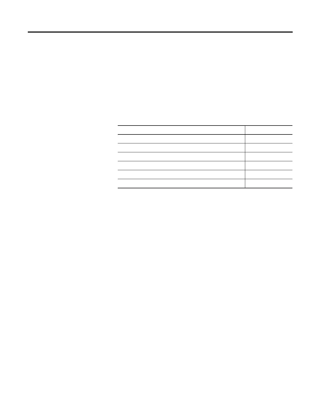
Topic Page
ControlLogix Redundancy Overview 111
Build a Redundant System 113
ControlNet Considerations in Redundant Systems 114
EtherNet/IP Considerations in Redundant Systems 115
Redundancy and Scan Time 116
Minimum System Requirements 116
 Loading...


