Rockwell Automation Publication 2099-UM001D-EN-P - December 2012 53
Kinetix 7000 Connector Data Chapter 3
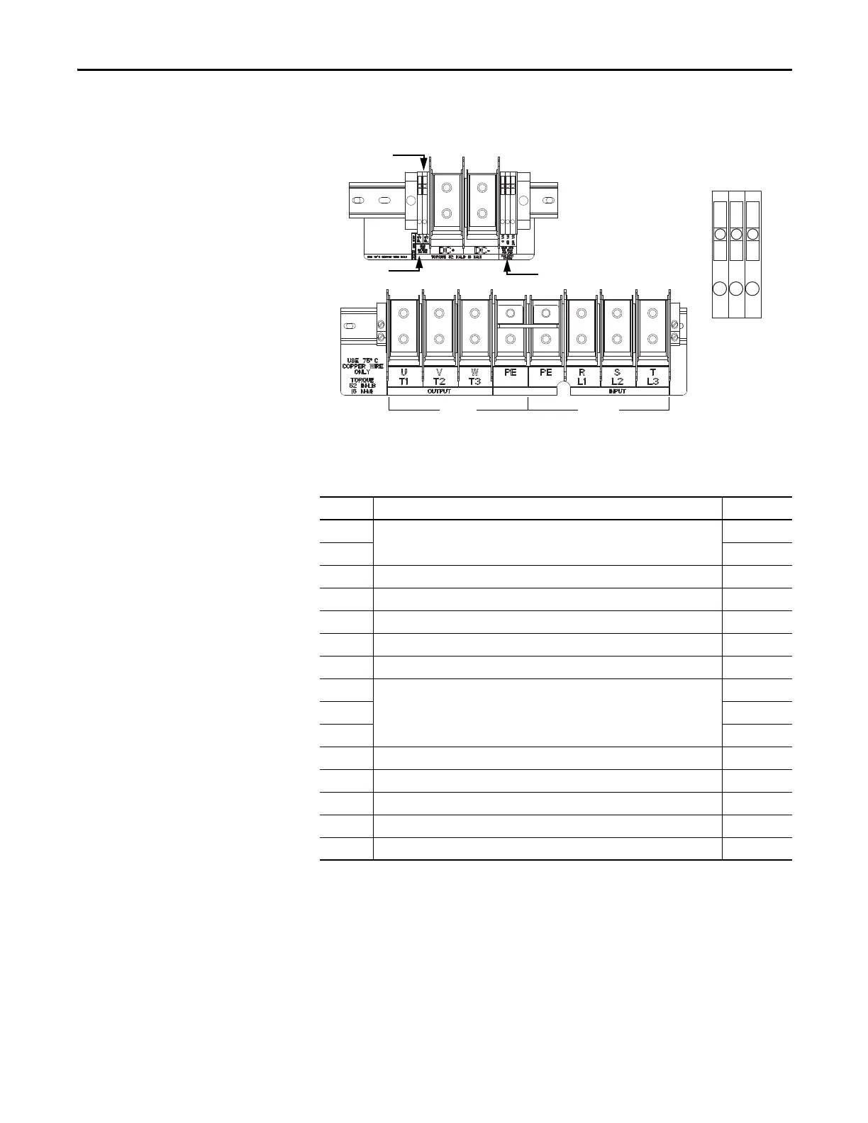
Figure 30 - 2099-BM11-S and 2099-BM12-S
Table 18 - Power Terminal Block
Terminal Description Name
DC+ DC Bus Power DC Bus (+)
DC- DC Bus (-)
PE Main Ground of the Drive System PE Ground
GND Motor Ground Motor Ground
U-T1 Motor Phase U Output U (T1)
V-T2 Motor Phase V Output V (T2)
W-T3 Motor Phase W Output W (T3)
R-L1 Main 380…480V AC +/-10% Input Power, Three-phase to R, S and T Input Terminals R
S-L2 S
T-L3 T
120VAC +120V AC Input for Fan Power VAC_FAN_1
240VAC +240V AC Input for Fan Power VAC_FAN_2
0VAC Fan Common GND_FAN
PS- For factory use only –
PS+ For factory use only –
FAN
PS+
PS-
Motor
AC Line
Fan Terminals
Enlarged View
0 VAC
120 VAC
240 VAC

 Loading...


