Rockwell Automation Publication 2099-UM001D-EN-P - December 2012 95
Connect the Kinetix 7000 Drive System Chapter 4
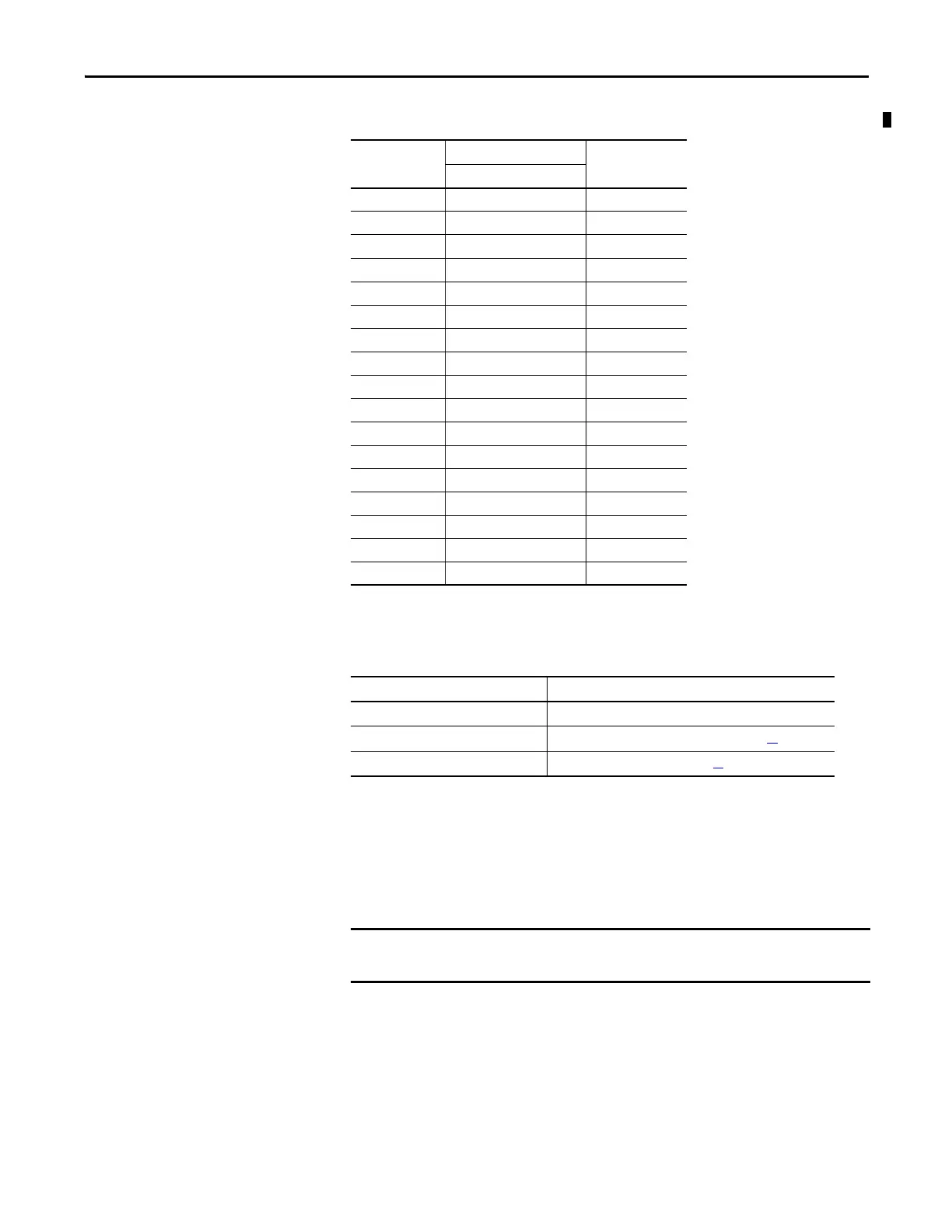
Table 46 - 2090-XXNFMF-Sxx and 2090-CFBMxDF-CDAFxx Feedback Cable
Wire Feedback and I/O
Connectors
Wire your feedback and I/O cables.
Connect Premolded Motor Feedback Cables
Motor feedback cables (with premolded connectors) plug directly into 15-pin
motor feedback (MF) connectors on Kinetix 7000 drive (no wiring is necessary).
Motor Circular DIN
Connector Pin
RDB-Bxxxxx-3/7 Motors
2090-K7CK-KENDAT
Pin
Signal
1Sine+ 1
2Sine- 2
3Cos+ 3
4Cos- 4
5Data+ 9
6Data-10
7CLK+ 7
8CLK- 8
9EPWR_5V 5
10 ECOM 6
11 Reserved –
12 Reserved –
13 TS+ 11
14 TS- –
15 Reserved –
16 Reserved –
17 Reserved –
To make this type of connection Go to
Premolded Cable Connect Premolded Motor Feedback Cables below.
Panel-mounted Breakout Board Wire Panel-mounted Breakout Board Kits on page 96
.
Low-profile Connector Wire Low-profile Connectors on page 98.
When using Bulletin 2090 cables with premolded connectors, tighten the
mounting screws (finger tight) to improve system performance.

 Loading...


