30 Rockwell Automation Publication 2099-UM001D-EN-P - December 2012
Chapter 2 Install the Kinetix 7000 Drive System
Bonding Multiple Subpanels
Bonding multiple subpanels creates a common low impedance exit path for the
high frequency energy inside the cabinet. Subpanels that are not bonded together
may not share a common low impedance path. This difference in impedance may
affect networks and other devices that span multiple panels.
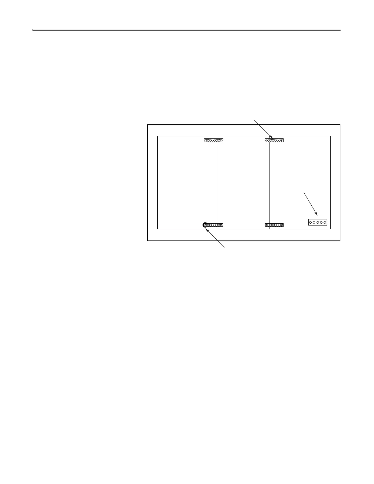
Figure 9 - Multiple Subpanels and Cabinet Recommendations
Establish Noise Zones
When designing a panel for a Kinetix 7000 system, observe the following
guidelines with additional attention to zone locations.
Bond the top and bottom of each subpanel to the cabinet using 25.4
mm (1.0 in.) by 6.35 mm (0.25 in.) wire braid.
Scrape the paint around each fastener to
maximize metal to metal contact.
Cabinet ground bus bonded
to the subpanel.

 Loading...


