Rockwell Automation Publication 2099-UM001D-EN-P - December 2012 49
Kinetix 7000 Connector Data Chapter 3
Auxiliary Feedback (AF) Connector Pinouts
For TTL devices, the position count will increase when A leads B. For sinusoidal
devices, the position count will increase when cosine leads sine.
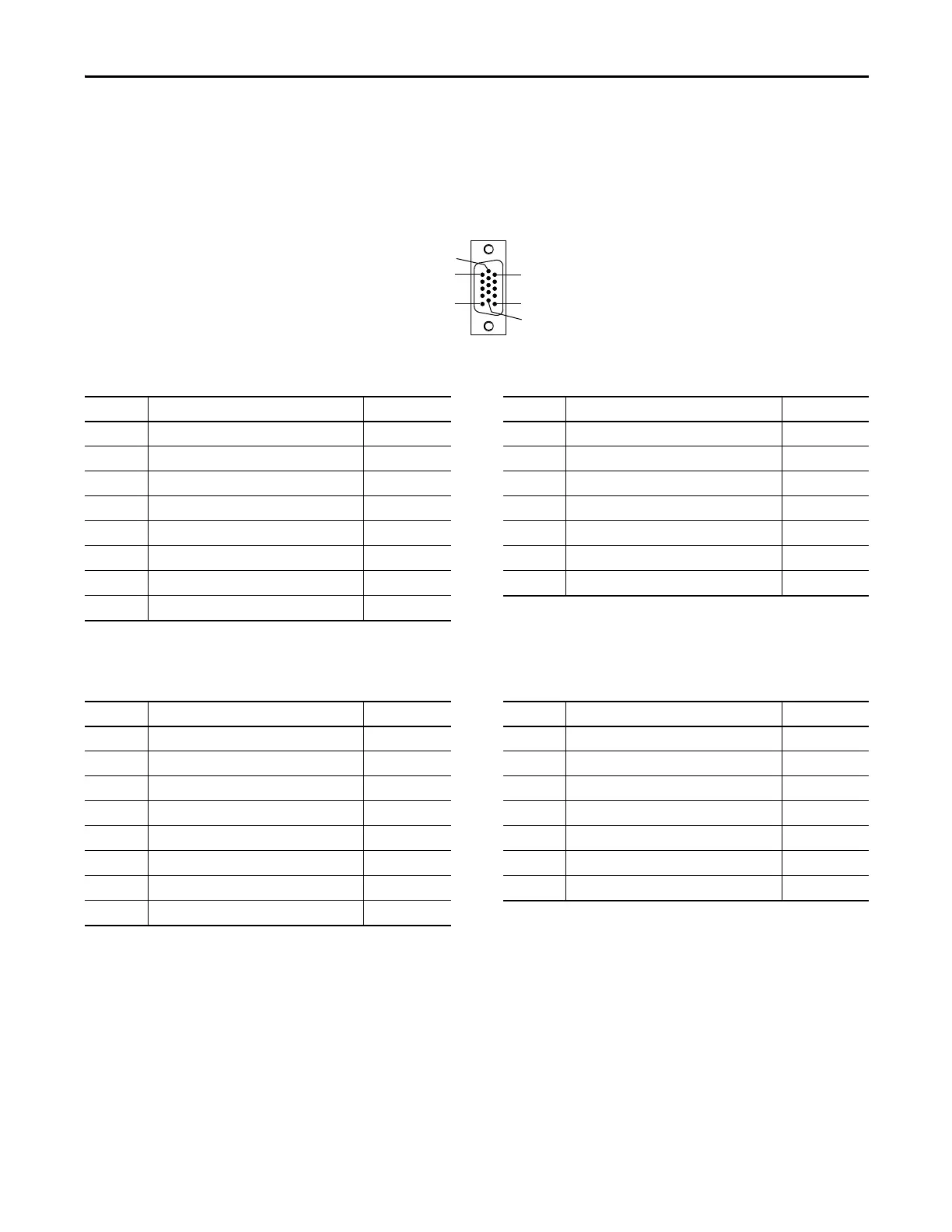
Figure 24 - Pin Orientation for 15-pin Auxiliary Feedback (AF) Connector
Table 14 - Stegmann Hiperface (SRS and SRM only)
Table 15 - TTL or Sine/Cosine with Index Pulse
Pin 1
Pin 11
Pin 10
Pin 5
Pin 6
Pin 15
Pin Description Signal Pin Description Signal
1 Sine differential input+ SIN+ 9 Reserved —
2 Sine differential input- SIN- 10 Hiperface data channel DATA-
3 Cosine differential input+ COS+ 11 Reserved —
4 Cosine differential input- COS- 12 Reserved —
5 Hiperface data channel DATA+ 13 Reserved —
6 Common ECOM 14 Encoder power (+5V) EPWR_5V
(1)
7 Encoder power (+9V) EPWR_9V
(1)
15 Reserved —
8Reserved —
(1) Encoder power supply uses either 5V or 9V DC based on encoder used.
Pin Description Signal Pin Description Signal
1 A+ / Sine differential input+ A+ / SIN+ 9 Reserved —
2 A- / Sine differential input- A- / SIN- 10 Index pulse- I-
3 B+ / Cosine differential input+ B+ / COS+ 11 Reserved —
4 B- / Cosine differential input- B- / COS- 12 Reserved —
5 Index pulse+ I+ 13 Reserved —
6 Common ECOM 14 Encoder power (+5V) EPWR_5V
(1)
7 Encoder power (+9V) EPWR_9V
(1)
15 Reserved —
8Reserved —
(1) Encoder power supply uses either 5V or 9V DC based on encoder used.
 Loading...


