36 Rockwell Automation Publication 2099-UM001D-EN-P - December 2012
Chapter 2 Install the Kinetix 7000 Drive System
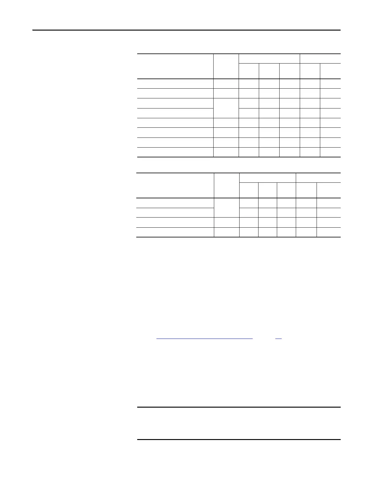
Table 6 - Line Interface Module
Table 7 - External Shunt Resistor Kit
Noise Reduction Guidelines for Drive Accessories
When mounting an AC (EMC) line filter or external shunt resistor refer to the
sections below for guidelines designed to reduce system failures caused by
excessive electrical noise.
AC Line Filters
Observe the following guidelines when mounting your AC (EMC) line filter.
See the Establishing Noise Zones (AC Power)
on page 33 for an example.
• Mount the ac line filter on the same panel as the Kinetix 7000 drive and as
close to the power input as possible.
• Good HF bonding to the panel is critical.
For painted panels, refer to the examples on page 29.
• Segregate input and output wiring as far as possible.
Wire/Cable Connector Zone Method
Very
Dirty
Dirty Clean Ferrite
Sleeve
Shielde
d Cable
VAC line (main input) IPL X
230V AC input APL X
VAC load (shielded option)
OPL
XX
VAC load (unshielded option) X
Control power output CPL X
MBRK PWR, MBRK COM P1L/PSL X
Status I/O IOL X
Auxiliary 230V AC P2L X
Wire/Cable Connector Zone Method
Very
Dirty
Dirty Clean Ferrite
Sleeve
Shielded
Cable
COL, DC+ (shielded option)
RC
XX
COL, DC+ (unshielded option) X
Thermal switch TS X X
Fan (if present) N/A X
CE test certification applies only to ac line filter and single drive. Sharing a
line filter with multiple drives may perform satisfactorily, but the user takes
legal responsibility.

 Loading...


