108 Rockwell Automation Publication 2099-UM001D-EN-P - December 2012
Chapter 5 Configure and Startup the Kinetix 7000 Drive System
Node Addressing Examples
The examples below illustrate how each axis in the fiber-optic ring is assigned a
node address. The ControlLogix platform is used in the examples, but the node
addressing is typical for Logix platforms.
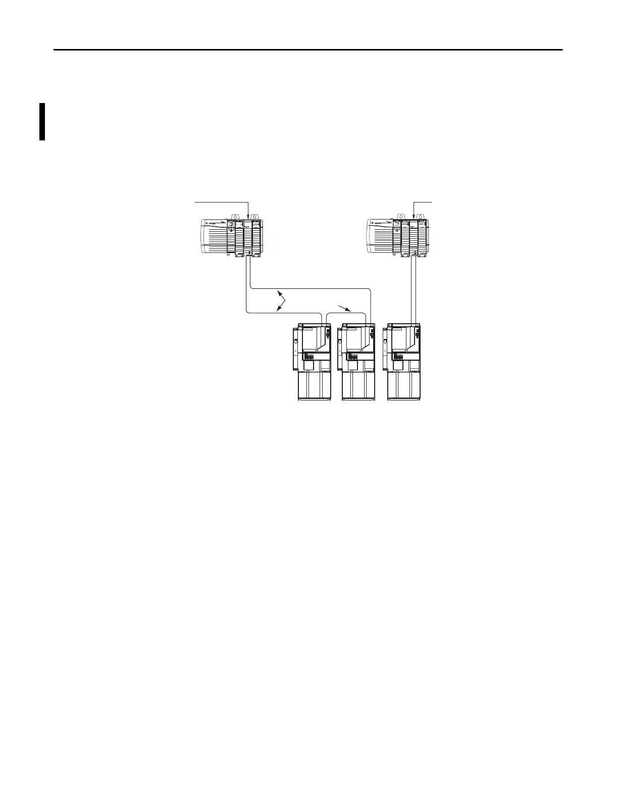
Figure 65 - Node Addressing Example 1
In this example, SERCOS interface module 1 controls Kinetix 7000 axes 1 and 2.
SERCOS interface module 2 controls Kinetix 7000 axis 3.
SERCOS interface
TM
Tx (rear)
Rx (front)
OK
CP
SERCOS interface
TM
Tx (rear)
Rx (front)
OK
CP
03 = Drive (axis 3) Node Address
02 = Drive (axis 2) Node Address
01 = Drive (axis 1) Base Node Address
SERCOS Fiber-optic Rings
1756-MxxSE SERCOS
interface Module 1
Kinetix 7000 Drive
System
Transmit Receive
1756-MxxSE SERCOS
interface Module 2
Transmit Receive
Logix Chassis/PCI Card
(ControlLogix chassis is shown)
Logix Chassis/PCI Card
(ControlLogix chassis is shown)
Transmit
Receive
Receive Transmit
You can mount the two SERCOS interface modules in two separate Logix
chassis (as shown above) or you can mount them in the same chassis.
Utilizing two SERCOS interface modules to control axes from a single Kinetix
7000 drive lets you reduce cycle times.
 Loading...


