42 Rockwell Automation Publication 2099-UM001D-EN-P - December 2012
Chapter 3 Kinetix 7000 Connector Data
Locate and Identify
Connectors and Indicators
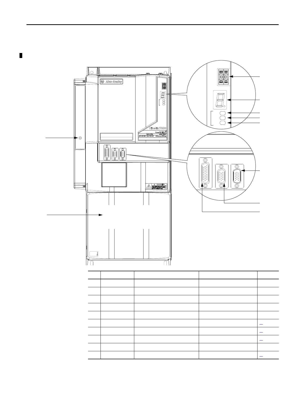
Although the physical size of the drives vary, the location of the connectors and
indicators is identical.
Figure 17 - Kinetix 7000 Front Panel Connectors and Displays
Status
Auxiliary
Feedback
Motor
Feedback
I/O
Fault/Status
SERCOS
CP_24VDC
CP_COM
CP
Node Address
Drive
Comm
Bus
Status
Fault/Status
SERCOS
Node Address
Drive
Comm
Bus
Auxiliary
Feedback
Motor
Feedback
I/O
Power terminal block located
behind protective cover.
2099-BM08-S shown
1
2
3
6
7
8
9
4
5
10
Item Designator/Label Description Connector See Page
1 Node Address SERCOS Node Address Switches – Chapter 6
2 Fault/Status Fault Status Display – Chapter 7
3 Drive Drive Status LED – Chapter 7
4 Comm Communication Status LED – Chapter 7
5Bus Bus Status LED – Chapter 7
6 AF Auxiliary Feedback Connector 15-pin high-density D-shell (male) 49
7 MF Motor Feedback Connector 15-pin high-density D-shell (female) 47
8 IOD Digital and Analog Input/Output Connector 26-pin high-density D-shell 45
9– Control Power Status LED – Chapter 7
10 PTB Power Terminal Block Terminal block 51

 Loading...


