92 Rockwell Automation Publication 2099-UM001D-EN-P - December 2012
Chapter 4 Connect the Kinetix 7000 Drive System
Wire Motor Output Power
Wire motor output power as described in Ta b le 40. See Power Terminal Block
(PTB) Connections on page 51
for more information.
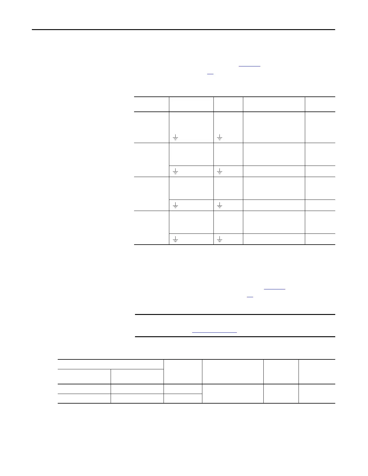
Table 40 - HPK-Series and MP-Series Servo Motor Power Connections
Wire the Motor Brake
Wire the motor brake (if applicable) as described in Ta ble 4 1. See Power
Terminal Block (PTB) Connections on page 51
for more information on the
motor power connections.
Table 41 - Motor Brake Connections
Notes: HPK-Series motor brake terminations are BR+ and BR-. RDD-Series
motors do not have a motor brake.
Kinetix 7000
Drive Cat. No.
Signal Terminal Recommended Wire Size
mm
2
(AWG)
Torque
N•m (lb•in)
2099-BM06-S
2099-BM07-S
2099-BM08-S
U / Brown
V / Black
w / Blue
Green/Yellow
U
V
W
25…2.5 (3…14) 1.8 (16)
2099-BM09-S U / Brown
V / Black
w / Blue
U
V
W
50…4 (1/0…12) 3.6 (32)
Green/Yellow 50…4 (1/0…12) 5 (44)
2099-BM10-S U / Brown
V / Black
w / Blue
U
V
W
70…10 (2/0…8) 15 (133)
Green/Yellow 50…4 (1/0…12) 5 (44)
2099-BM11-S
2099-BM12-S
U / Brown
V / Black
w / Blue
U
V
W
100…10 (4/0…8) 12 (104)
Green/Yellow 50…4 (1/0…12) 5 (44)
Use surge suppression when controlling a brake coil.
See Figure 81 on page 172
.
Motor Brake Terminal (Signal) Drive Terminal
(Signal)
Recommended Wire Size
mm
2
(AWG)
Strip Length
mm (in.)
Torque Value
N•m (lb•in)
Bulletin MPL
w/Bayonet Connector
Bulletin MPx
w/Circular DIN Connector
A (BR+) F (BR+) 2 (GPR1+)
2.5 (14) 10 (0.38)
0.5…0.6
(4.4…5.3)
C (BR-) G (BR-) 3 (GPR1-)
 Loading...


