Disassembly / Assembly Diagrams D-5
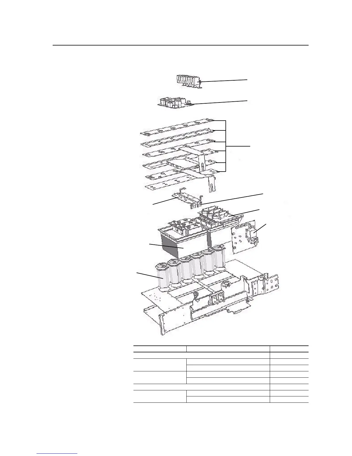
Figure D.4 Phase V and W Power Structure Components
Table D.D Phase V and W Power Structure Components Part Numbers
Snubber Capacitor Assembly
Precharge (Rectifying) Board
DC Link Bus Bar Kit - 500V
Bus Bar Bridge DC-
Bus Bar Bridge DC+
Output Power Module
Rectifying Module
Gate Driver Board
Electrolytic
Capacitor
480V Shown
Part Name Spare Part No.
Cover Plate NA
DC Link Bus Bar Kit 500V NA
690V NA
Electrolytic Capacitor ELKO 3300Pf 420V Bus Capacitor - 400/480V 20-PP01005
ELKO 5600Pf 420V Bus Capacitor - 600/690V 20-PP01099
Snubber Capacitor Assembly 20-PP10019
Gate Driver Board - 480V SK-H1-GDB1-F11D
690V SK-H1-GDB1-F11E

 Loading...


