EasyManua.ls Logo

Allen-Bradley PowerFlex 750 Series - Page 494

Allen-Bradley PowerFlex 750 Series
548 pages
To Next Page IconTo Next Page
To Previous Page IconTo Previous Page
Loading...
494 Rockwell Automation Publication 750-PM001N-EN-P - February 2017
Appendix D Using DeviceLogix
Functional Block Programming
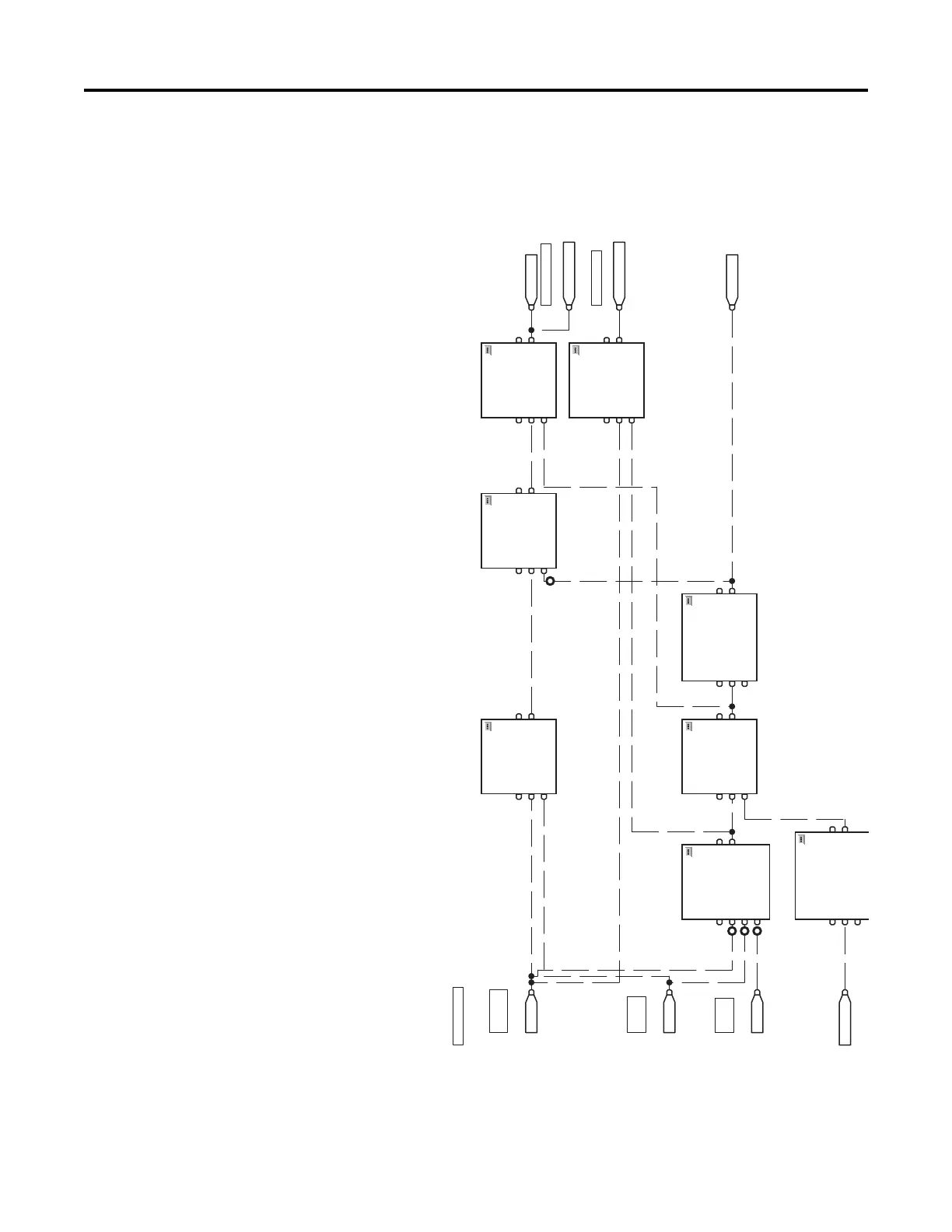
This example consists of 16 blocks that are shown in the following figure.
Figure 95 - Control Circuit
Start
SpdRef Sel 1
2BAND
Boolean And
EnableIn
In1
In2
In3
6BAND
Boolean And
EnableIn
In1
In2
7SETD
Set Dominant
EnableIn
Set
Reset
DI P 2
DI P 1
DI P 3
Acti ve
Stop is momentarily
asserted ( 2 secs)
5PULR
Pulse Timer with Reset
EnableIn
TimerEnable
Reset
4BAND
Boolean And
EnableIn
In1
In2
8SETD
Set Dominant
EnableIn
Set
Reset
Stop
1BOR
Boolean Or
EnableIn
In1
In2
Run at High Rate
SpdRef Sel 0
Run at Normal R ate
Cr it ical H igh
Level Sensor
High Level
Sensor
Low Level
Sensor
Mi nim um P u mp Ti me
3TONR
Timer On Delay with Reset
EnableIn
TimerEnable
Reset
CONTROL CIRCUIT

Table of Contents

Other manuals for Allen-Bradley PowerFlex 750 Series

Related product manuals