Rockwell Automation Publication 750-PM001N-EN-P - February 2017 495
Using DeviceLogix Appendix D
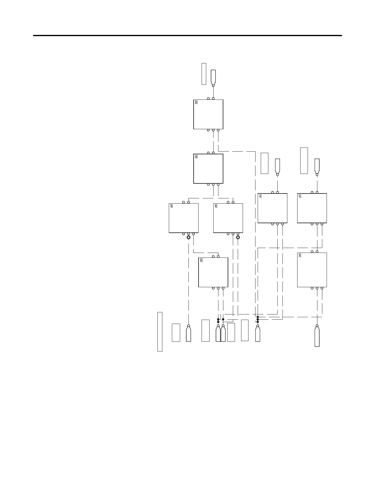
Figure 96 - Fault/Alarm Circuit
Example 5: Utilizing the Real-Time Clock
This example demonstrates how to utilize the PowerFlex 750-Series drive Real-
Time Clock in a DeviceLogix program.
Example logic requirements:
• Run the drive Monday through Friday between 7:45 a.m. and 5:15 p.m
DIP 4
Acti ve
11 BAND
Boolean And
EnableIn
In1
In2
12 BOR
Boolean Or
EnableIn
In1
In2
13 SETD
Set Dominant
EnableIn
Set
Reset
14 SETD
Set Dominant
EnableIn
Set
Reset
16 SETD
Set Dominant
EnableIn
Set
Reset
DOP 1
DOP 2
DOP 3
FAULT / ALARM CIRCUIT
9BOR
Boolean Or
EnableIn
In1
In2
DIP 3
DIP 1
DIP 2
Sensor Fault
Critical H igh
Level Fault
Too Much Time
Alarm
Critical H igh
Level Sensor
Low Level
Sensor
High Level
Sensor
Alarm / Fault
Reset PB
15 TONR
Tim er On D elay with Re set
EnableIn
TimerEnable
Reset
10 BAND
Boolean And
EnableIn
In1
In2

 Loading...


