Rockwell Automation Publication CNET-UM001F-EN-P - February 2018 69
I/O information is presented as a structure of multiple fields dependent on
the specific features of the I/O module. The name of the structure is based on
the location of the I/O module in the system. Each I/O tag is automatically
created when you configure the I/O module in Logix Designer software.
Each tag name follows this format:
Location:SlotNumber:Type.MemberName.SubMemberName.Bit
Address Variable Definition
Location Identifies the network location by using one of these values:
• LOCAL—Local DIN rail or chassis
• ADAPTER_NAME—Remote adapter or bridge that you
specify
SlotNumber Slot number of I/O module location in its chassis.
Type Identifies one of these types of data:
• I—Input
• O—Output
• C—Configuration
• S—Status
MemberName Specific data from the I/O module depending on the type of
data the module can store. For example, Data and Fault are
possible fields of data for an I/O module. Data is the common
name for values that are sent to or received from I/O points.
SubMemberName Specific data related to a MemberName.
Bit (optional) Specific point on the I/O module depending on the size of the
I/O module (0...31 for a 32-point module).
I/O information is available in the Controller Tags portion of your Logix
Designer project. You can monitor or edit the tags.
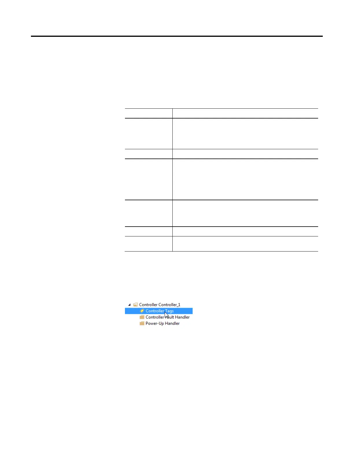
To access distributed I/O, within the Controller Organizer of Logix Designer
application, double-click Controller Tags.
I/O
 Loading...


