Hardware Reference 29
C613-03020-00 REV K
Switch Cables and Loopback Plugs
This section describes how to make cables for connecting the switch’s
interfaces to networks, terminals, and printers. How to make loopback plugs
for testing switch interfaces is also described.
Descriptions of cables and loopback plugs for PIC interfaces can be found in
the Port Interface Card Hardware Reference.
Terminal and Modem Cables
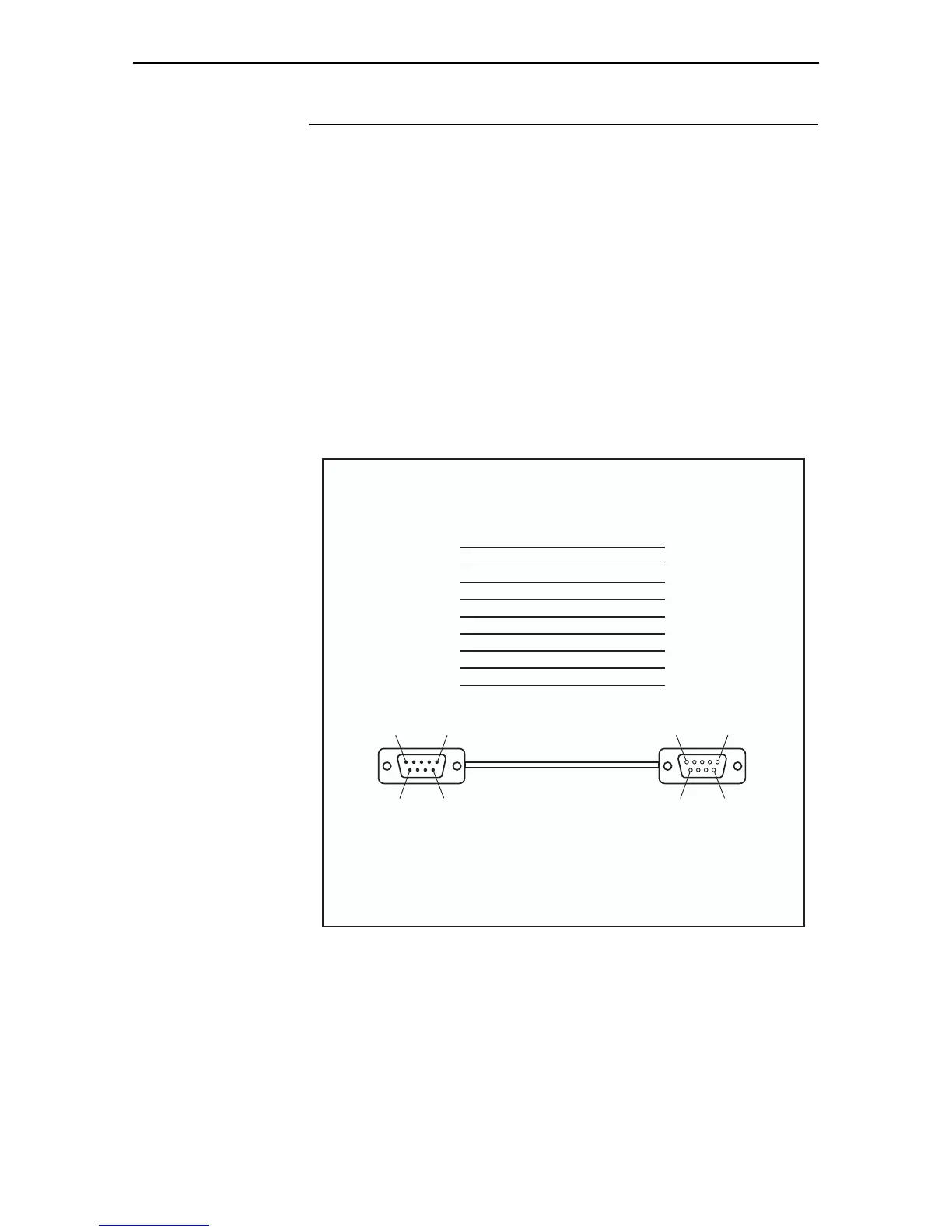
Figure 20 shows how to wire cables to connect a standard VT100 compatible
terminal, or a modem, to the switch’s RS-232 Terminal Port.
For NEBS compatibility, the cable must be shielded and grounded at both ends,
especially if permanently connected.
Figure 20: Pin wiring diagram for a standard DB9 male to female terminal cable
Notes:
(1) → Output from switch; ← Input to switch.
(2) Cable version 1.0.
DB9MDB9Fsw
1
2
3
4
5
6
7
8
9
1
2
3
4
5
6
7
8
9
Cable
Pin 9
Pin 6
Pin 5
Pin 1
DB9 Female Pin View
Pin 6
Pin 9
Pin 1
Pin 5
DB9 Male Pin View
DB9 Male
(to switch/DCE)
DB9 Female
(to PC/terminal/DTE)
Not connected
→ (TXD)
← (RXD)
← (CD)
(GND)
→ (DTR)
← (CTS)
→ (RTS)
← (RING)
(DCD)
(RXD)
(TXD)
(DTR)
(GND)
(DSR)
(RTS)
(CTS)
(RING)
 Loading...


