24 Rapier Series Switch
C613-03020-00 REV K
Redundant Power Supply
AC models of Rapier Switches have a Redundant Power Supply (RPS)
connector on their rear panel. Table 8 lists the connector’s pin numbers and pin
functions.
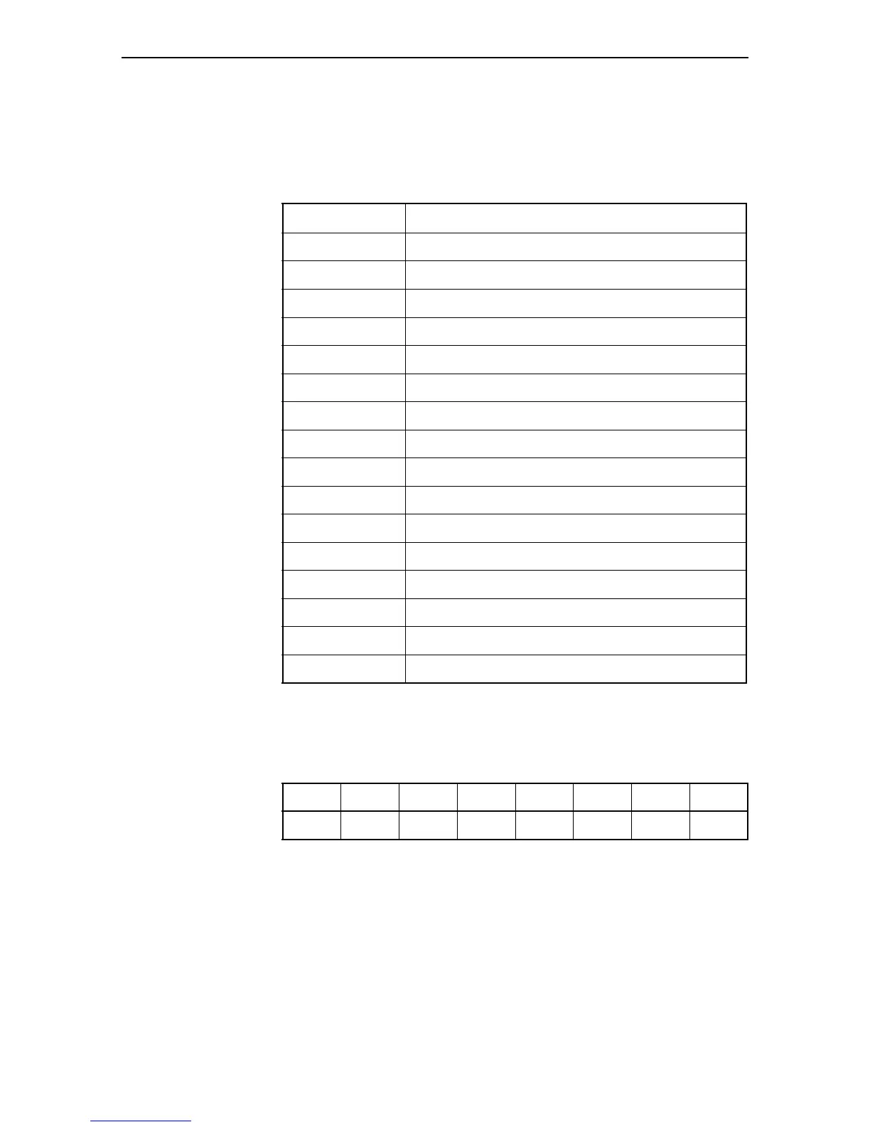
Table 9 illustrates the connector’s pin layout.
Pin 16 is at the connector’s top left, while pin 1 is at its lower right.
Table 8: RPS Connector Pin Numbers and Functions
Pin Number Function
1 +12 VDC
2 Remote Sense (RS) +5 VDC
3 Remote Sense (RS) Ground
4 Remote Sense (RS) +3.3 VDC
5 Redundant Power Supply (RPS) Present
6 Ground (+3.3 VDC Return)
7 Ground (+5 VDC Return)
8+5 VDC
9 Ground (+12 VDC Return)
10 +3.3 VDC
11 Ground (+3.3 VDC Return)
12 +3.3 VDC
13 Ground (+3.3 VDC Return)
14 +3.3 VDC
15 +5 VDC
16 Ground (+5 VDC Return)
Table 9: RPS Connector’s Pin Layout
16 15 14 13 12 11 10 9
87654321
 Loading...


