Hardware Reference 21
C613-03020-00 REV K
Switch Interfaces
This section provides pin assignments for the asynchronous console ports,
RJ-45 switch ports, and the Redundant Power Supply (RPS) connector.
If you have installed a Port Interface Card (PIC), pin assignments for these can
be found in the Port Interface Card Hardware Reference (which is included on the
Documentation and Tools CD-ROM bundled with your switch, or can be
downloaded from www.alliedtelesis.com/support/software).
Asynchronous Console Port
All Rapier switches except the Rapier 48w have a single asynchronous serial
RS-232 console port, labelled “RS-232 Terminal Port /asyn0”. The Rapier 48w
switch has two asynchronous serial RS-232 console ports, labelled “asyn0” and
“asyn1”.
The RS-232 console ports are used to connect the switch to a management
device. For management purposes the switch’s software can be accessed from a
terminal, a PC running terminal emulation software, or from a remote location
via a modem connection. You can also use the RS-232 console ports to establish
a network connection from a remote site using SLIP and a modem.
The console ports have a DCE female connector. This allows the use of a
straight-through cable when connecting the switch to a terminal or PC. Output
from the show asyn command will, however, still have a DTE perspective. The
internal DTE pin roles are listed in Table 3.
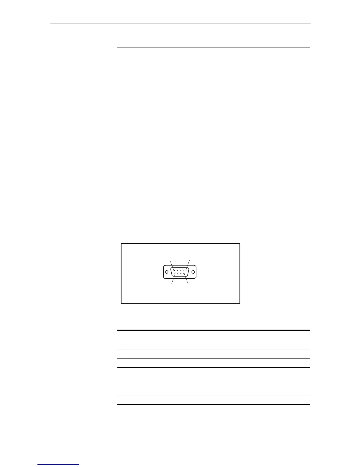
Figure 18: RS-232 Terminal Port Pin Numbers
See “Terminal and Modem Cables” on page 29 for more information on
connection options for the RS-232 console ports.
Table 3: Internal DTE pin roles
Pin Role
2TXD
3RXD
4CD
5GND
6DTR
7CTS
8RTS
Pin 9
Pin 6
Pin 5
Pin 1
DB9 Female Pin View
 Loading...


