EasyManuals Logo

Allied Telesis Rapier Series User Manual

Allied Telesis Rapier Series
65 pages
To Next Page IconTo Next Page
To Previous Page IconTo Previous Page
Page #8 background imageLoading...
Page #8 background image
8 Rapier Series Switch
C613-03020-00 REV K
Rapier Switch Models
This section provides hardware descriptions for individual switch models.
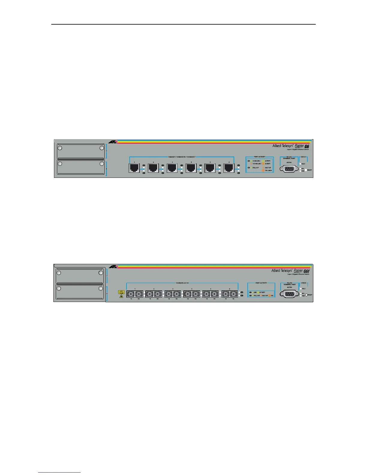
Rapier G6
(Figure 1)
6-port 100BASE-TX/1000BASE-T (RJ-45 connectors)
Two 10/100/1000BASE uplink bays
Layer 3 Managed Switch
Figure 1: Front panel of the Rapier G6
Rapier G6F-LX/SC
(Figure 2)
6-port 1000BASE-LX (SC fibre connectors)
Two 10/100/1000BASE uplink bays
Layer 3 Managed Switch
Figure 2: Front panel of the Rapier G6F/LX
135246

Other manuals for Allied Telesis Rapier Series

Questions and Answers:

Question and Answer IconNeed help?

Do you have a question about the Allied Telesis Rapier Series and is the answer not in the manual?

Allied Telesis Rapier Series Specifications

General IconGeneral
BrandAllied Telesis
ModelRapier Series
CategorySwitch
LanguageEnglish

Related product manuals