Hardware Reference 9
C613-03020-00 REV K
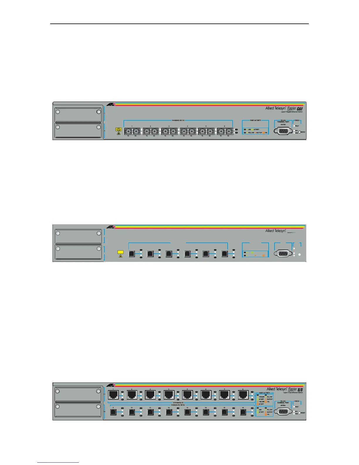
Rapier G6F-SX/SC
(Figure 3)
■ 6-port 1000BASE-SX (SC fibre connectors)
■ Two 10/100/1000BASE uplink bays
■ Layer 3 Managed Switch
Figure 3: Front panel of the Rapier G6F/SX
Rapier G6F-SX/MT-RJ
(Figure 4)
■ 6-port 1000BASE-SX (MT-RJ fibre connectors)
■ Two 10/100/1000BASE uplink bays
■ Layer 3 Managed Switch
Figure 4: Front panel of the Rapier G6F/MT
Rapier 8/8MT
(Figure 5)
■ 8-port 10BASE-T/100BASE-TX (RJ-45 connectors)
■ 8-port 100BASE-FX (MT-RJ fibre connectors)
■ Two 1000BASE uplink bays
■ One Network Service Module bay, with support for various WAN interface
cards
■ One PCI Accelerator Card (PAC) Slot
■ Layer 3 Managed Switch
Figure 5: Font panel of the Rapier 8/8MT
7
8
RS-232
TERMINAL PORT
ASYN0
STATUS
RESET
FAU LT
PWR
RPS
6
54321
PORT ACTIVITY
LINK
HALF DUP
FULL DUP
ACTIVITY
COL
CLASS 1
LASER PRODUCT
DO NOT STARE
INTO BEAM
1000BASE-SX / MT-RJ
Layer 3 Gigabit Ethernet Switch
L/A
D/C
L/A
D/C
L/A
D/C
L/A
D/C
L/A
D/C
L/A
D/C
L/A
D/C
Rapier
G6f
135 72468
 Loading...


