EasyManua.ls Logo

Alpha XM2-300HP - Fig. 1-7 Inverter Module Connections

Alpha XM2-300HP
64 pages
Print Icon
To Next Page IconTo Next Page
To Previous Page IconTo Previous Page
Loading...
1.2 XM2-300HP Layout, continued
1.2.2 Inverter Module Overview, continued
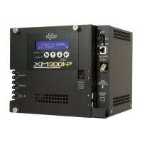
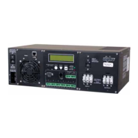
Battery Switch:

does not transfer to standby mode, the inverter is disabled, and the battery charger
cannot charge the battery.
Battery Input Connector

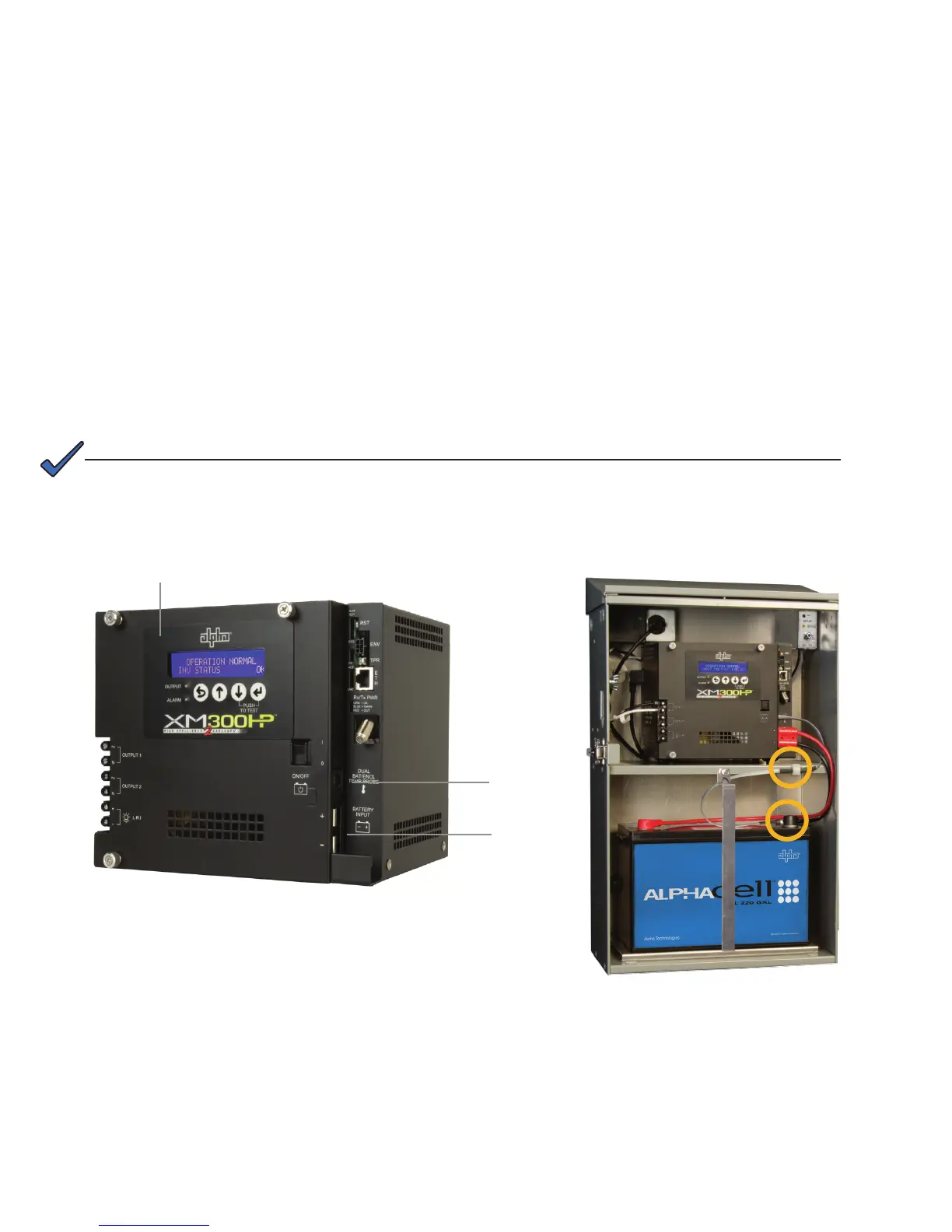
Temp Probe Connector:-


the enclosure. The second sensor attaches to the negative terminal of the battery
and monitors battery temperature. To install, connect the ring terminal onto the nega-

Fig. 1-7, Inverter Module Connections
Temp Probe
Connector
Smart
Display
Battery Input
Connector


NOTE:
Fig. 1-8, Temperature Probe Locations
18
017-877-B1-001 Rev. A

Table of Contents