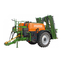
Layout and function of the basic implement
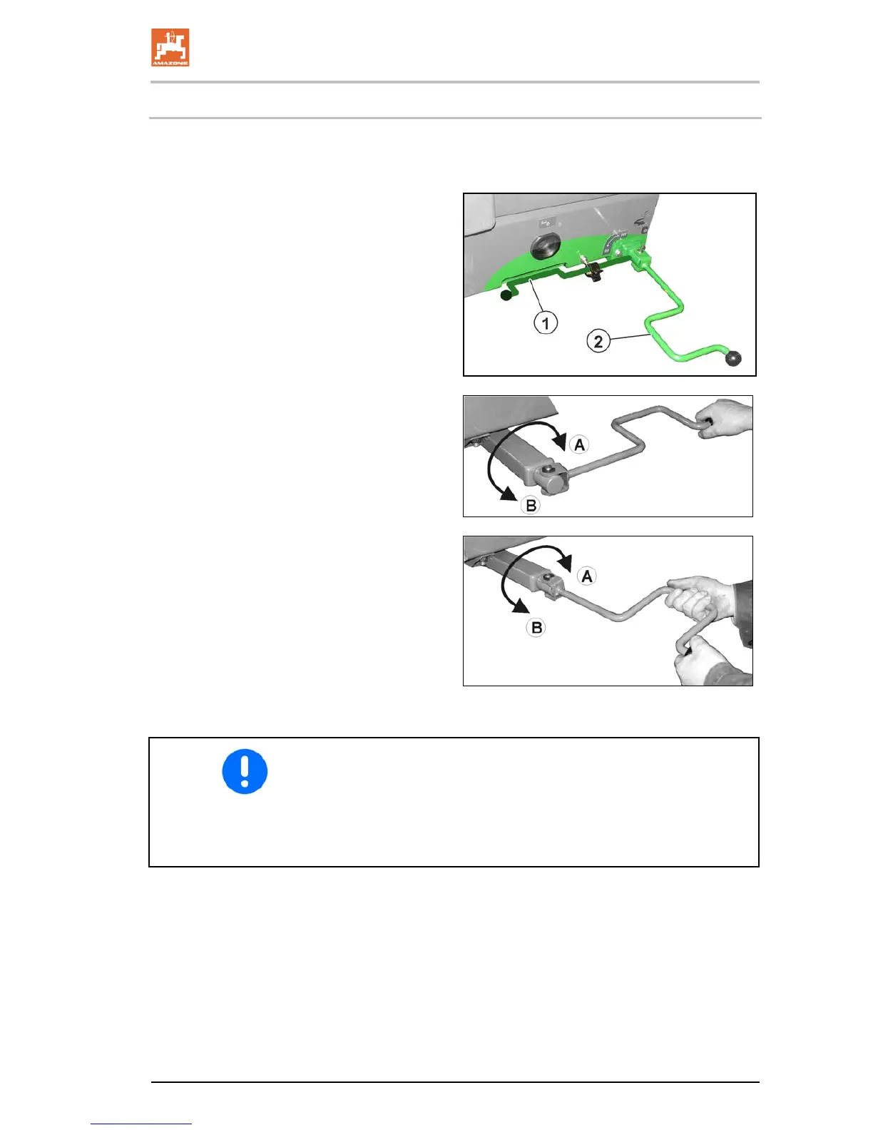
The applied parking brake secures the uncoupled implement against
accidental rolling away. The parking brake is actuated with the spin-
dle and cable pull when turning the crank.
(1) Crank; locked in resting position
(2) Crank in operating position
new
• Crank position for releasing / applying in the
end area.
(the parking brake requires approx. 20 kg
manual force to be applied).
• Crank position for quick releasing / apply-
ing.
(A) Apply the parking brake.
(B) Release the parking brake.
• Correct the setting of the parking brake if the spindle's tension is
no longer sufficient.
• Ensure that the cable pull is not lying or rubbing against other
vehicle parts.
• When the parking brake is released, the cable pull must be
slightly slack.

 Loading...