No. Component Function
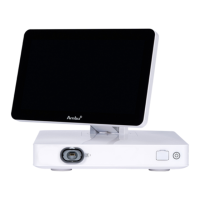
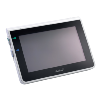
5 Power button Turns the power ON or switches to STANDBY mode.
6 Base Contains the main unit.
7 Power cable Connects the displaying unit to a power outlet.
8Wi-Fi antenna
Connect Wi-Fi antenna to the displaying unit for
improved Wi-Fi signal.
9Positioning arm
Enables manual positioning of the touch screen.
The screen can be adjusted horizontally and
vertically as well as rotated.
10 Video output ports (2x DVI-D) Enable connection to external monitor or external
medical imaging recorder. See section 6.1 for details
on the difference between using DVI-D and 3G-SDI
on the displaying unit.
11
Video output ports (2x 3G-SDI)
12 Wi-Fi antenna connector Enables connection of Wi-Fi antenna.
13 USB 3.0 ports Enables connection of external USB flash drives.
14 LAN port Enables connection to ethernet.
15 USB 2.0 ports Enables connection of external USB flash drives.
16
Trigger output ports
(2 x 3.5 mm jack)
Enable connection to an external medical imaging
recorder to transfer trigger signals.
17
Trigger output ports
(2 x D-SUB9)
18 Power inlet Enables connection to power cable.
19
Connector for potential
equalization cable
Enables bonding of electrical products to eliminate
potential differences between conductive parts.
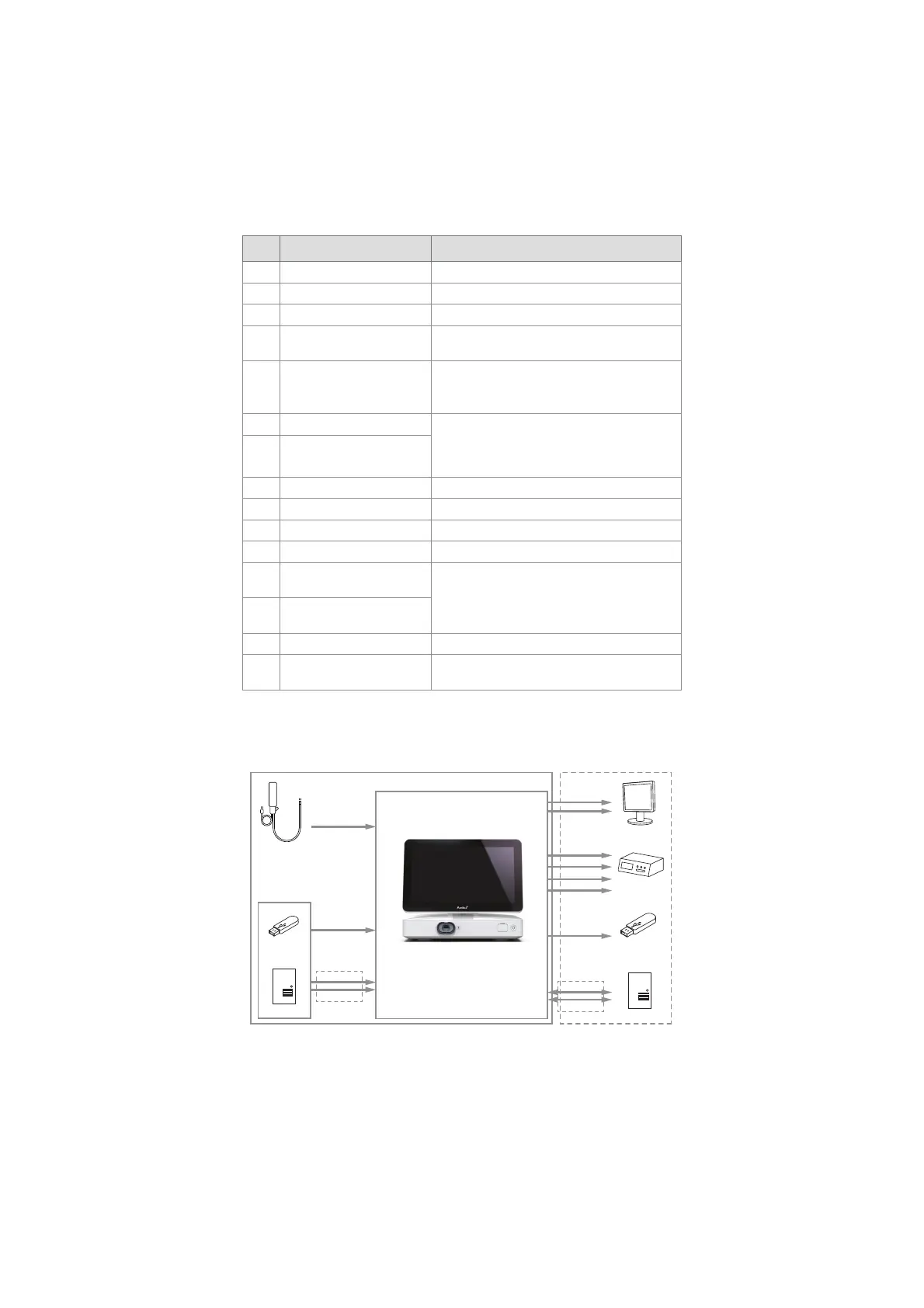
2.5. System Overview
A complete Ambu Imaging System is configured as illustrated in the figure below. The various
connections are described in more detail in chapter 6.
DVI-D
3G-SDI
DVI-D
USB 2.0/3.0
DICOM
USB Flash Drive
Server
Wi-Fi
LAN
PACS Server
External Monitor
External Medical
Imaging Recorder
Visualization
Device
Image and Video
Streams
USB 3.0
Ambu Displaying Unit
External Connection OptionsAmbu Imaging System
Software
Update/Upgrade
Wi-Fi
LAN
Recordings/
Log Files
3G-SDI
3.5 mm Jack
D-SUB9
8