8
© AMETEK, Inc.
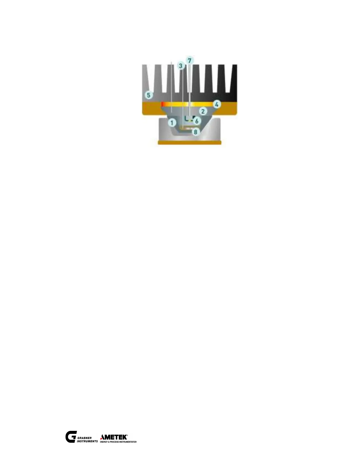
3.3 Measuring method
A Ni-plated aluminum cup (1) with a sample is resting in the sample cup holder. For the test, the sample cup is lifted to
the temperature-controlled oven (2), forming the test-chamber with a metal to metal seal. A thermocouple (3) is
immersed into the sample to measure the temperature. The temperature of the oven is controlled by Peltier elements
(4) and an air-cooled heat sink (5). The vapor is ignited by a high voltage arc (6) inside the test-chamber. At the flash
point, the pressure inside the sealed measuring chamber is increased significantly, which is detected by a built-in
pressure transducer (7). A rotating magnet and a small magnet (8) inside the the sample cup provides stirring.
The measuring program is adjusted. Even though MINIFLASH FP(H) VISION measures according to a standardized
method (ASTM D 6450 or ASTM D 7094), all parameters can be programmed freely.
3.4 Patent
The MINIFLASH FP(H) Vision is protected by following patents:
WO 2011140576
US 8950934
EP 2569617
AT 509743
You can search for the patents here:
Espacenet http://worldwide.espacenet.com
United States Patent and Trademark Office http://patft.uspto.gov/
 Loading...