CONNEX
TM
User Guide
16
Unit and the Air Unit. The bit rate of this control can be configured in the S.BUS Rate field
using the CONNEX Management application, as described in the Configuring the Link section on
page 42.
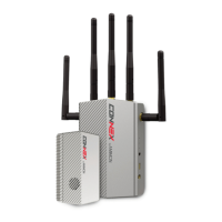
Five Rx Antennas Connectors: The five provided antennas must be screwed onto these
connectors.
On/Off Switch: Set this switch to On in order to power on the Ground Unit.
OSD Button: Enables/disables the OSD display. The OSD display presents a screen of
telemetry MAVLink-based information collected by the CONNEX system on the monitor
connected to the Ground Unit, such as Air Unit flight parameters, height, direction, signal
strength and so on. You may refer to the Ground Unit – On Screen Display (OSD) section on
page 30 for more information. By default, OSD is enabled (displayed). Pressing this button
disables OSD and pressing this button again redisplays it.
Link Button: The CONNEX system supports up to four Ground Units per Air Unit. The Ground
Unit is provided out-of-the-box to automatically search for and connect to the Air Unit that is
provided in the same box. The Link button enables you to connect additional Ground Units to
the same Air Unit. You may refer to the Multicasting to Multiple Ground Units section on page 34
for a description of this procedure.
HDMI Port: Enables the display of the received video. Connect this port to a monitor’s HDMI
port using the provided Standard HDMI cable.
Battery Plate Screws: Four screws are provided on the bottom of the Ground Unit for
connecting a battery plate. The battery plate is an optional accessory and is not included. It is
available to be purchased from the Amimon’s website.
For a description of the Air Unit LEDs, you may refer to:
• Table 6: Ground Unit – Power LED
• Table 7: Ground Unit – Video LED
• Table 8: Ground Unit – Network LED