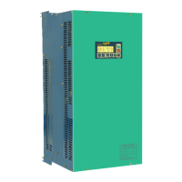
Axpert-Eazy AC Variable Frequency Drive
A.17
13
A
No.
Fault Name Causes & Countermeasures
38
Temperature Fault
1. A trouble may have occurred in the cooling fan/ blower.
Replace it if necessary.
2. The ambient temperature may have risen.
Lower the ambient temperature (less than 50 °C for 400V series or
less than 40 °C for 500V / 600V series).
3. The carrier frequency may be set too high.
4. The temperature switch (thermostat) is not connected or loosely
connected at J16.
Disconnect thermostat switch connection at J16 and ensure that
the thermostat shows short circuit. Reconnect thermostat properly.
39
Connected) Fault
1. The thermistor is not connected or loosely connected at J13.
Disconnect the thermistor and ensure that the thermistor shows
resistance greater than 2.2 kΩ but less than 60 kΩ. Reconnect
thermistor properly.
40
Fail
1. Same as per
U Phase Current Sensor Fail
41
Fail
42
1. Check the thermistor sensor.
43
Connected) Fault
1. The temperature switch (thermostat) is not connected or loosely
connected at J16. Disconnect thermostat switch connection at J16
and ensure that the thermostat shows short circuit. Reconnect
thermostat properly.
44
Fault
1. RUN did not turn OFF after engaging the external brake.
Check that the settings are correct, or that the RUN command is
OFF within C321.
45
Ext Brake Ans Error Fault
1. The brake command and answer signal from the brake do not
match. Check the answer signal from the brake.
46
Sensor Fail**
1. Loose connection of hall current sensor cable connected at TB1 to
TB6 of PCA-2049A.
Switch off the unit and remove the cable. Check for proper crimping
of cable on both sides. If found abnormal, replace the cable and
check again.
2. One or more current sensor has failed.
Remove connector TB1 to TB6
and reset the fault. If the fault can
be reset, find out which current sensor has failed.
3. If after removing connector TB1 to TB6, the problem persists,
replace PCA- 2049A.
47
Sensor Fail**
48
Sensor Fail**
49
Sensor Fail**
50
Sensor Fail**
51
Sensor Fail**
52
Sensor Fail**
53
Sensor Fail**
54
Sensor Fail**
55
Sensor Fail**
56
Sensor Fail**