Accessories
19
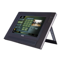
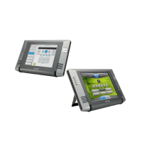
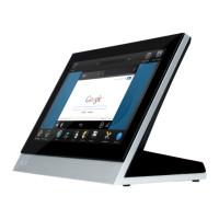
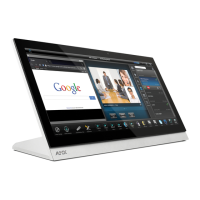
MVP-9000i 9" Modero® ViewPoint® Touch Panel with Intercom
2. Select the knockout to be removed from the top of the box. The box has two knockouts, at the top left and the top
right.
3. Connect the PS-POE-AT High-Power PoE Injector to a power source. Connect the PS-POE-AT to an Ethernet
switch on the network via one length of Ethernet cable and insert one length of Ethernet cable for connection to the
Wall Docking Station.
4. Run the Ethernet cable through the knockout into the back box. Pull out about six inches (15.25cm) of cable into the
back box to facilitate installation of the MVP-WDS-9.
5. Slide the plastic back box into the hole, being careful not to twist or pinch the cable, and set it flush with the wall.
Make sure that all of the lockdown wings are folded into their slots before attempting to insert the box.
For ease of installation, the inside of the box has the direction “UP” labeled for reference.
6. Extend the wings on the sides of the box by tightening the screws inside the box.
Not all of the wings must be extended to lock the box in place, but extending a minimum of the top and
bottom wings is highly recommended.
Apply enough pressure to the screw head to keep the box flush with the wall: this ensures that the wing will
tighten up against the inside of the wall.
7. Attach the included snap-on ferrite to the Ethernet cable, as close to the RJ-45 connector as possible. Attach the
cable to the Ethernet Port (FIG. 16).
Make sure to measure the size of the intended hole before starting to cut it. Cutting
the hole slightly smaller than the dimensions to allow for adjustments is highly
recommended.
To assist with wiring, and to avoid mechanical stresses on the wire and the
mechanism of the Wall Docking Station, the top left knockout, when viewing the
device from the rear, is preferred for use for Ethernet installation. Use the top right
knockout for USB cable connection.
Make absolutely certain that the box is in its intended position. Once the box
lockdown wings are extended within the box’s hole within the wall, removing the box
will be extremely difficult without damaging the wall in the process.
The maximum recommended torque to screw in the wings on the plastic back box is
5 IN-IBS [5(NI-CM)]. Applying excessive torque while tightening the wing screws,
such as with powered screwdrivers, can strip out the wings or damage the plastic
back box.
FIG. 16 MVP-WDS-9 - Ethernet cable path
Knockout placement
in back box
Recommended Ethernet installation
Recommended USB installation
Ethernet port
Ferrite installation
position
Recommended
Ethernet cable
path
 Loading...