Upgrading Firmware
97
MVP-9000i 9" Modero® ViewPoint® Touch Panel with Intercom
9. In the Virtual NetLinx Master Settings dialog box, click OK to close the box.
10. In the Communications Settings dialog box, click OK to close the box.
11. In the Master Communications Settings dialog box, click OK to save your settings and return to the main NetLinx
Studio application.
12. Click the OnLine Tree tab in the Workspace window to view the devices on the Virtual System. The default System
value is 1.
13. Right-click on the Empty Device Tree/System entry and select Refresh System to re-populate the list.
14. The OnLine Tree should now display the connection to the device. The Connection Status Icon on the device may
take up to five seconds to register the connection.
Step 3: Confirm and Upgrade the firmware via the USB port
Use the CC-USB Type-A to Mini-B 5-wire programming cable to provide communication between the mini-USB
Program port on the touch panel and the PC. This method of communication is used to transfer firmware Kit files and
TPD4 touch panel files.
1. Verify that the direct USB connection (Type-A on the panel to mini-USB on the panel) is configured properly, using
the steps outlined in the previous two sections.
2. With the panel already configured for USB communication and the Virtual Master setup within NetLinx Studio,
refresh the Online Tree pane.
3. After the Communication Verification dialog window verifies active communication between the Virtual Master and
the panel, click the OnLine Tree tab in the Workspace window (FIG. 109) to view the devices on the Virtual
System. The default System value is 1.
4. Right-click on the System entry (FIG. 109) and select Refresh System to re-populate the list. Verify the panel
appears in the OnLine Tree tab of the Workspace window.
The panel will not appear as a device below the virtual system number, in the Online
Tree tab, until both the system number used in step 14 for the Virtual NetLinx Master
is entered into the Master Connection section of the System Settings page and the
panel is restarted.
A mini-USB connection is only detected after it is installed onto an active panel.
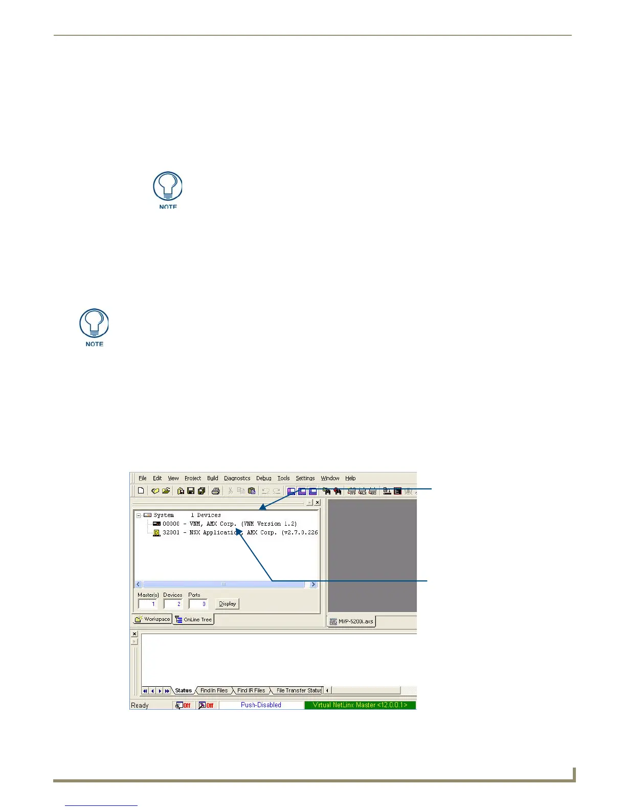
FIG. 109 NetLinx Workspace window (showing panel connection via a Virtual NetLinx Master)
Virtual Master firmware
version and device number
MVP panel firmware version
and device number
 Loading...