Page 16
Installation
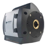
2.2 - CONNECTORS
There are six connections points on the iXon3 as shown in gure 8 above. There are four industry-standard SMB (Sub
Miniature B) connectors, details as follows:
• Fire (please refer to pages 51 - 63)
• Shutter(seepage 64)
• Arm (please refer to pages 51 - 63)
• Ext.Trig(ExternalTriggerInput) (please refer to pages 51 - 63)
Theseareusedtosend/receiveTriggerandFiresignals.TheSMBoutputs(Fire&Shutter)areCMOScompatible&series
terminated at source (i.e. in the camera head) for a 50Ω cable.
NOTES:
1. The termination at the customer end should be high impedance (>1K) as an incorrect impedance match
could cause errors with timing and triggering.
2. The External Trigger Input SMB is TTL level & CMOS compatible and has 470 impedance.
3. Signal diagrams of these connections can be found on page 79.
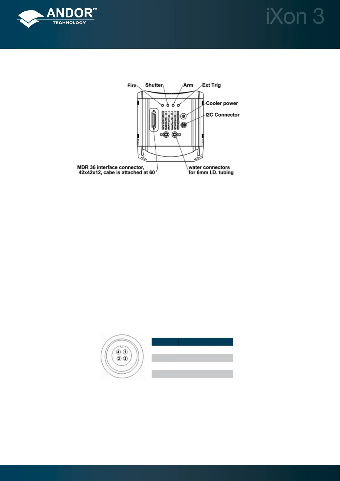
There is an I2C connection point and the pin-outs for this are shown in Figure 9 below:
The connection for the 26 pin interface between the camera and the PCI controller card is made via an MDR 36
connector shown in gure 8 above.
The Cooler Power connection is for the Power Supply Block (PSB) described on page 11.
Figure 8: iXon3 connectors
PIN FUNCTION
1 I2C DATA
2 I2C
3 + 5V
4 GROUND
Figure 9: I2C connection (facing in) with pin-outs
 Loading...