Page 21
Features & Functionality
3.1.2 - EM Gain & Read Noise
As explained on the previous pages, EMCCD sensors allow the detected signal to be amplied on the actual sensor
itself before being readout through the output amplier and digitized by the Analog to Digital (A/D) converter. The reason
that this on-chip-multiplication process gives such a spectacular improvement in low light detection is that it negates the
effect of any electronic noise that may be generated by the read out electronics.
AllCCDcamerashaveanassociatedminimumelectronicnoiseoorwhichisoftentermedtheRead Noise of the
system. Read noise is produced during the readout process mostly by the output amplier but also has contributions
from the digitization electronics. This sets the minimum signal level that can be detected by the camera, as any signal
level below the read noise level will be indistinguishable from the read noise itself.
Read noise has therefore been the major limiting factor for low light level detection in CCDs for many years until the
introduction of EMCCD cameras by Andor Technology in 2000. By applying EM gain, a weak signal that would otherwise
be indistinguishable from the read noise can be amplied above the read noise level and thus be read out as a useful
signal. This amplication of the signal before being read out effectively reduces the read noise level of the camera and
even at relatively modest EM gain settings the effective read noise can be reduced to less than 1 electron r.m.s.
OneotherpointtonoteisthatsincereadnoiseincreaseswithincreasedreadoutratetheapplicationofEMgainreally
comes into its own at higher readout rates as any increase in the read noise can be overcome simply by increasing the
EM gain. For example, an iXon3 897 typically has a read noise of 50 electrons rms when reading out at 10MHz. This can
easilybereducedto<1electronbyapplying>x50EMgain.
3.1.3 - EM Gain ON vs EM Gain OFF
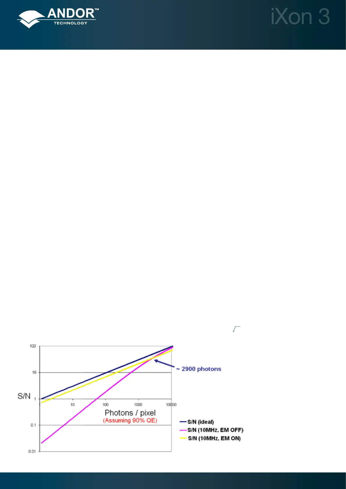
Figure 13 below shows Signal to Noise (S/N) plots derived from the specications of the back-illuminated iXon3
EMCCDs, read out at 10MHz for a photon wavelength at which the Quantum Efciency (QE) of the sensor is assumed
to be 90%. Such plots are very useful to gauge at what signal intensity it becomes appropriate to use EM Gain to
increaseS/N.
Itisclearthatat10MHzreadout,oneneedstoencounterrelativelyintensesignalsof>2900photons/pixelbeforeit
becomesadvantageoustooperatewithEMGainoff.Notethatthe“ideal”curverepresentsapureSignaltoShotNoise
ratio and is shown for reference – if the camera had no sources of noise, this is what the curve would appear like. Even
withEMGainturnedonweencounteruniformlylowersignaltonoisethantheidealcurve.Thisisduetotheinuenceof
Multiplicative Noise, which has the effect of increasing the shot noise by a factor of
2 or ~1.41.
Figure 13: EM Gain ON vs. EM-
Gain OFF signal to noise plots for
back-illuminated iXon3 EMCCDs at
10MHz readout speed (applies to
897, 860 and 888 models).
 Loading...