Page 30
Features & Functionality
3.3.4 - Output amplier selection
A number of the EMCCD sensors in the iXon3 range have dual output ampliers, an electron multiplying output amplier
and a conventional output amplier. This increases the versatility of the camera as the EM amplier can be selected for
fast imaging in low light conditions whilst the conventional amplier can be selected where more light is available and a
slower readout with its associated lower read noise and higher dynamic range is preferred.
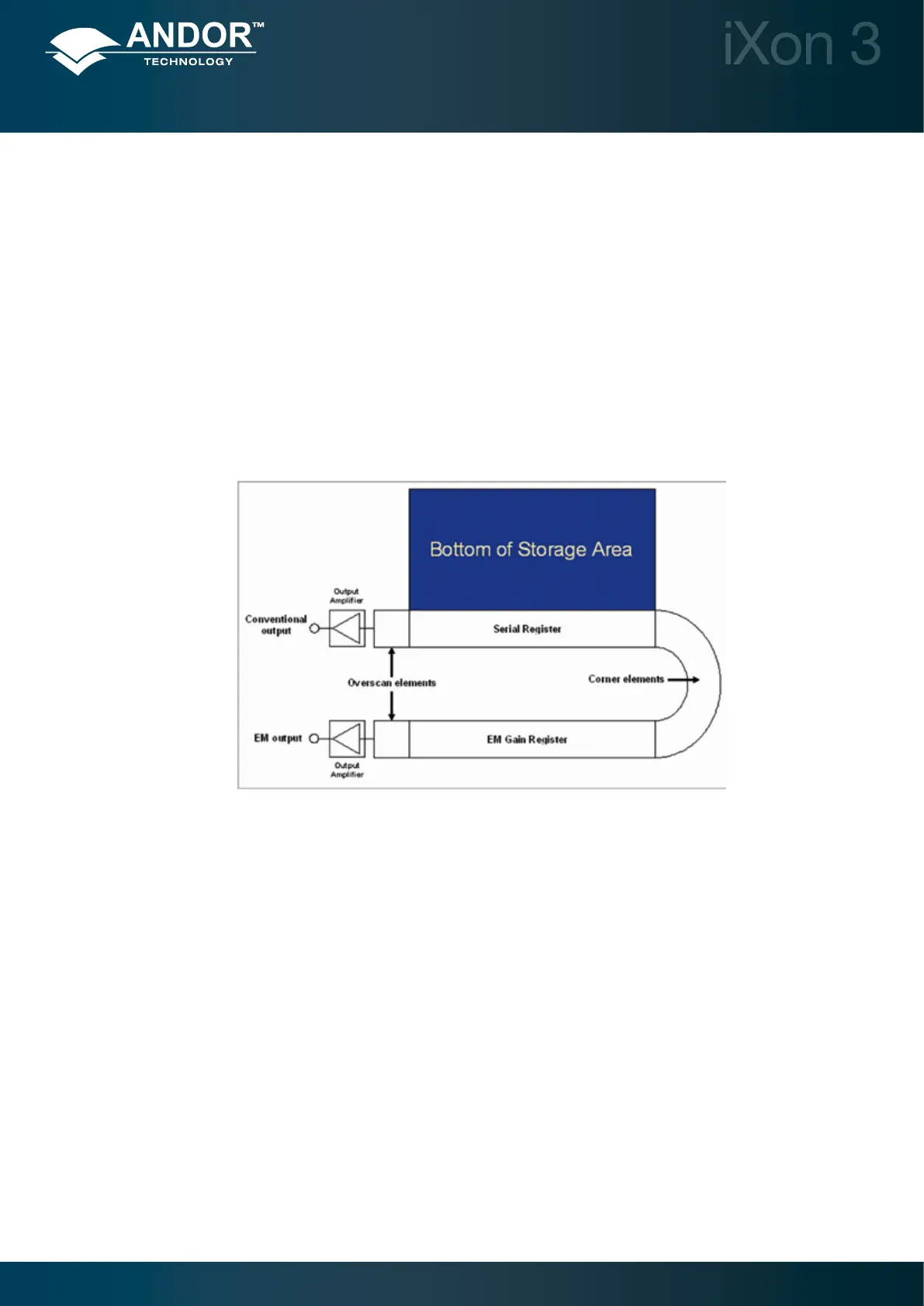
Figure 20 below details schematically the readout structure on sensors with both output ampliers present. From this
it can seen that when reading out through the EM amplier accumulated charge will move to the right along the serial
register and then into the EM gain register. When the conventional output amplier is selected the charge to be read
out will move along the serial register to the left then be transferred directly into the conventional output amplier. This
change in direction has the effect of producing mirror images when comparing raw data from the two output ampliers.
Some software packages will automatically reverse the image orientation of one of the output ampliers to allow direct
comparison of images. The user should consult their software manual to verify if this is the case.
3.3.5 - Baseline Optimization
3.3.5.1 - Baseline Level and Baseline Offset
The baseline or bias level is an electronic offset added to the output signal from the EMCCD sensor to ensure that the
displayed signal level is always a positive number of counts. This baseline level often tends to increase with decreasing
sensor cooling temperature. For all iXon3 cameras it is factory calibrated to approximately 400 counts at a cooling
temperatureof-75°C.
NOTES:
• Atwarmertemperaturesthebaselinelevelwilldecreaseandmaymovebelowzeroresultinginasignal
of zero counts being displayed. This can be overcome either by moving to a lower cooling temperature
or by using the baseline offset option which adds up to 1000 counts to the baseline level.
• Converselyatcoldertemperaturesthanthecalibrationtemperaturethebaselinemayincreaseslightly
and this can be countered by using the baseline offset option to subtract up to 1000 counts from the
baseline level.
Figure 20:
Sensor readout structure
 Loading...