11
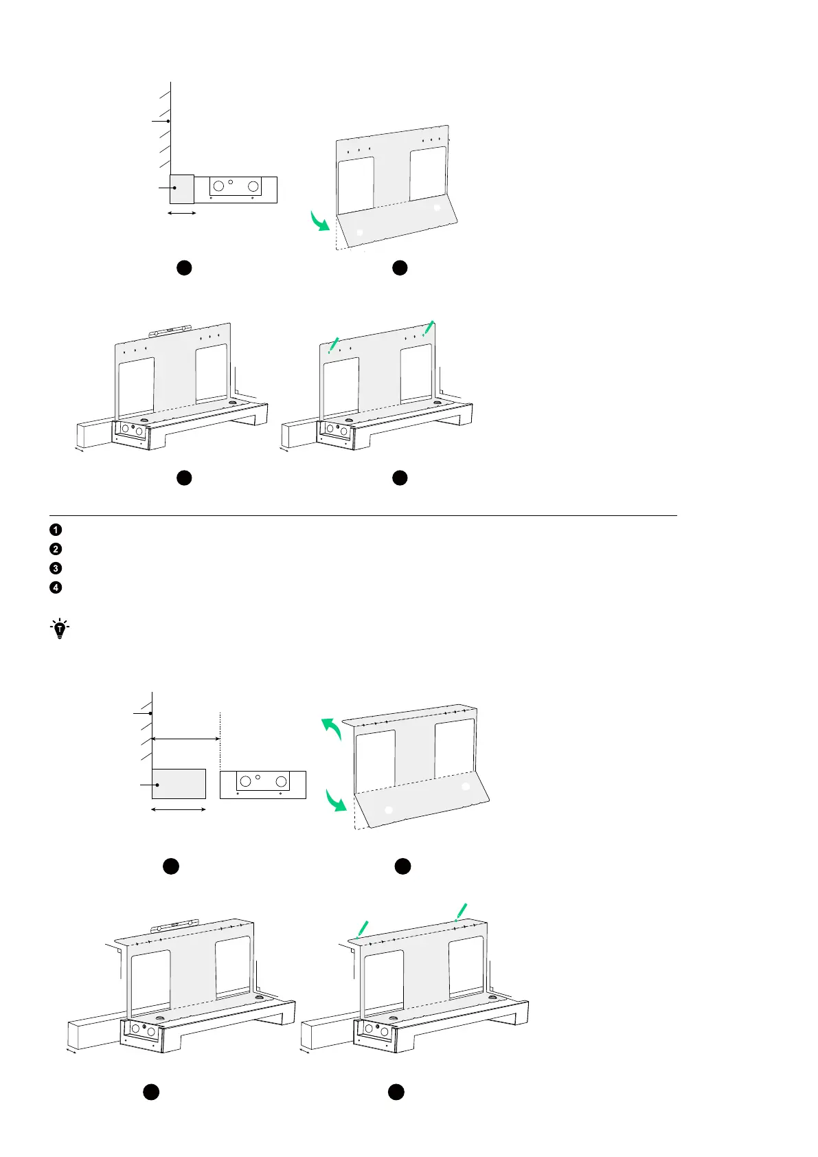
Figure: Mark pilot holes for the first module if the baseboard is 0-15 mm thick.
21
4
3
0-15 mm
Baseboard
Wall
Top
Bottom
90°
0-15 mm
Top
Bottom
90°
0-15 mm
Top
Bottom
If the baseboard is between 16 and 70 mm thick, follow these steps to mark pilot holes for the first module.
Keep a distance of 70 mm between the floor mounting base and the wall surface.
Fold the positioning card (included with the power module package) along the top and bottom creases.
Align the card with the top of the floor mounting base and use a level to ensure it is horizontal.
Select and mark a hole on each side based on the wall conditions to secure the first module.
If anchoring to a wall with studs, select position A for studs spaced 508 mm apart, position B for studs spaced 406
mm apart, or position C for studs spaced 304 mm apart.
Figure: Mark pilot holes for the first module if the baseboard is 16-70 mm thick.
2
1
43
Bottom
Top
≥ 16 mm
70 mm
Top
Bottom
90°
90°
Top
Bottom
90°
90°
16-70 mm
Baseboard
Wall