23
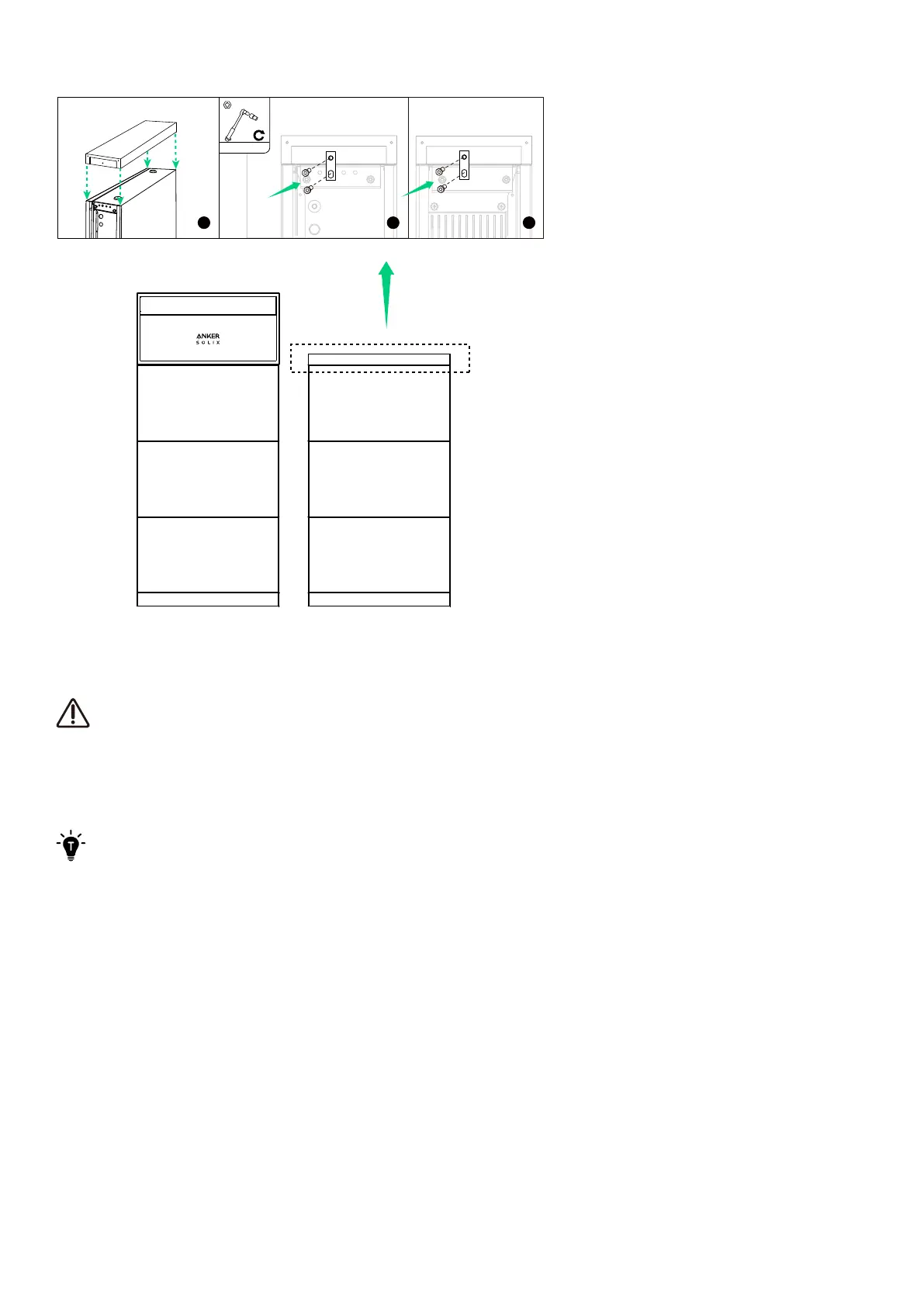
Figure: Install the top cover to the second column.
6. Electrical Connections
·
Before connecting cables, ensure the BAT switch on the power module is o.
·
Depending on local requirements, the wiring can be installed through conduits or cable glands.
·
Anker SOLIX X1 is only compatible with the specified power sensors (Model: SDM230-Modbus V1, DTSU666).
·
The inverter has not been tested to AS/NZS 4777.2:2020 for multiple inverter combinations so combinations should
not be used or external devices should be used in accordance with the requirements of AS/NZS 4777.1.
For the wiring diagrams, refer to “Appendix A. System Wiring Diagrams”.
6.1 Internal Connections
Connect One Column of Modules
To connect one column, which generally consists of a power module and a maximum of three battery modules, follow the
steps below.
1. Remove the dustproof plugs from all the modules' BMS ports and power ports (BAT+ and BAT-).