05
3.3 Battery Module
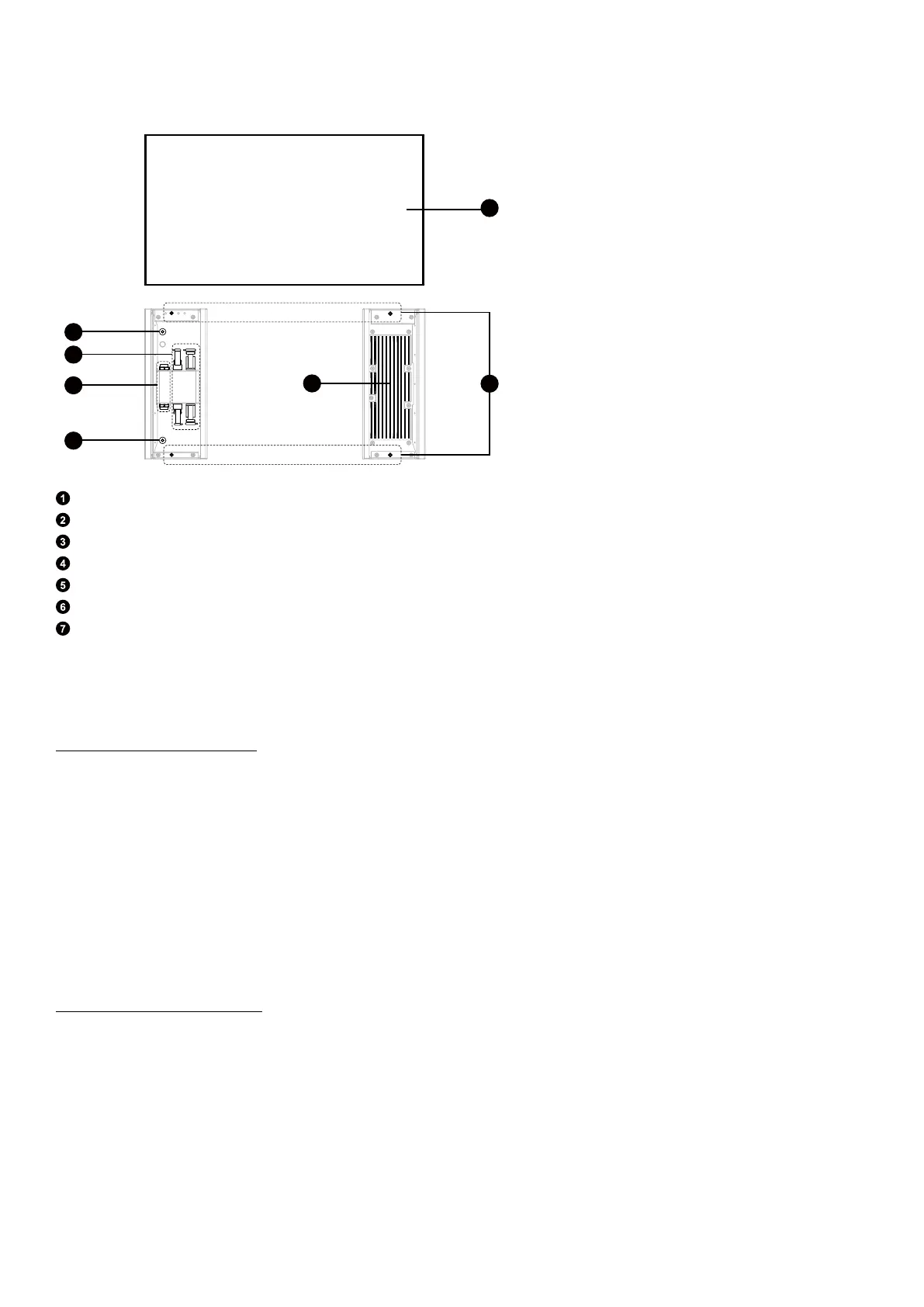
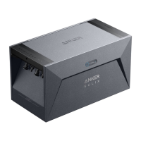
Figure: Appearance of the battery module.
2
4
3
5
1
6
BMS BAT- BAT+
BMS
BAT-
BAT+
7
Battery module
Internal ground point
DC power ports (BAT+ / BAT–)
BMS ports
Internal ground point
Heat sink
Screw holes for locking modules
4. Pre-Installation
4.1 Select an Installation Site
1. Environment Requirements:
·
Do not place the modules near a wall facing the maximum sunlight direction (usually south for the northern hemisphere, or
north for the southern hemisphere) or in an area exposed to direct sunlight, fire, or explosive materials.
·
Ensure the site is protected from potential hazards such as floods.
·
The maximum operating altitude is 4,000 m.
·
Do not install equipment in living spaces or habitable areas of dwelling units, such as living rooms.
·
Do not install the equipment outdoors in salt-aected areas to prevent corrosion. These areas typically include regions
within 300 (± 50) meters of the coast or prone to sea breezes*. In such areas, install the equipment indoors or in a sheltered
location.
*Note: Regions prone to sea breezes may vary depending on weather conditions (e.g., typhoons, monsoons) and terrain
features (e.g., dams, hills).
2. Load-Bearing Requirements:
The power and battery modules can be installed on either the floor or wall, while the backup controller is exclusively wall-
mountable.
·
Concrete / Masonry: Minimum strength requirements are 18 MPa for concrete, 12 MPa for clay brick, and 11 MPa for
masonry. Use the self-tapping screws with plastic anchors (M6×50 mm) and expansion bolts (M8×70 mm) to fully embed
them into the wall. Prior to mounting, inspect the surface and avoid using weak compositions.
·
Blocking / Wood Studs: Mount the modules directly onto the wood studs, which should be spaced 508 mm / 20 in, 406 mm
/ 16 in, or 304 mm / 12 in apart. Use the self-tapping screws (M6×50 mm, included) to fully embed them into the studs.
·
Other Types of Walls: Verify that the selected walls meet the load bearing requirements and choose appropriate screws. For
wall mounting, choose a wall capable of supporting the full weight of the equipment.
- Power module: 20 kg
- Battery module: 51 kg