33
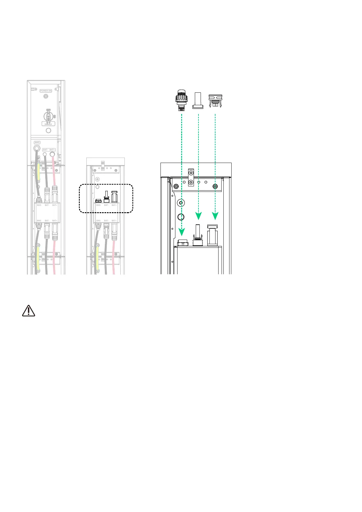
4. Seal unused ports.
On the top battery module in the second column, insert an RJ45 connector (with 2×120Ω terminating resistor, included) into
the BMS port, a female dustproof cap (included) into the negative DC power port (BAT-), and a male dustproof cap (included)
into the positive DC power port (BAT+).
Figure: Seal unused ports.
BMS BAT- BAT+
BAT
SWITCH
BAT
SWITCH
BMS
BAT- BAT+
POWER ON
BMS BAT- B AT+
BMS BAT- B AT+
BMS BAT- B AT+
BMS BAT- B AT+
BMS
BAT-
BAT+
BMS BAT- B AT+
BMS BAT- B AT+
BMS BAT- B AT+
BMS BAT- B AT+
BMS BAT- B AT+
BMS
BAT-
BAT+
BMS BAT- B AT+
6.2 External Connections
The following steps detail how to connect the power module to dierent external devices.
Residual Current Monitoring Device
The power module includes an integrated universal current-sensitive residual current monitoring unit. This unit will
disconnect the power module from the mains power immediately if a fault current with a value exceeding the limit is
detected.
If an external Residual Current Device (RCD) is mandatory, the switch must be triggered at a residual current of 30 mA
(recommended), or it can be set to other values according to local regulations. For example, in Australia, the power
module can use an additional 30mA (type B) RCD in installations.
However, if an external RCD (type B recommended) is mandatory, the switch must be triggered at a residual current of
30 mA (recommended). Local standards may allow for the use of RCDs with other specifications.