32
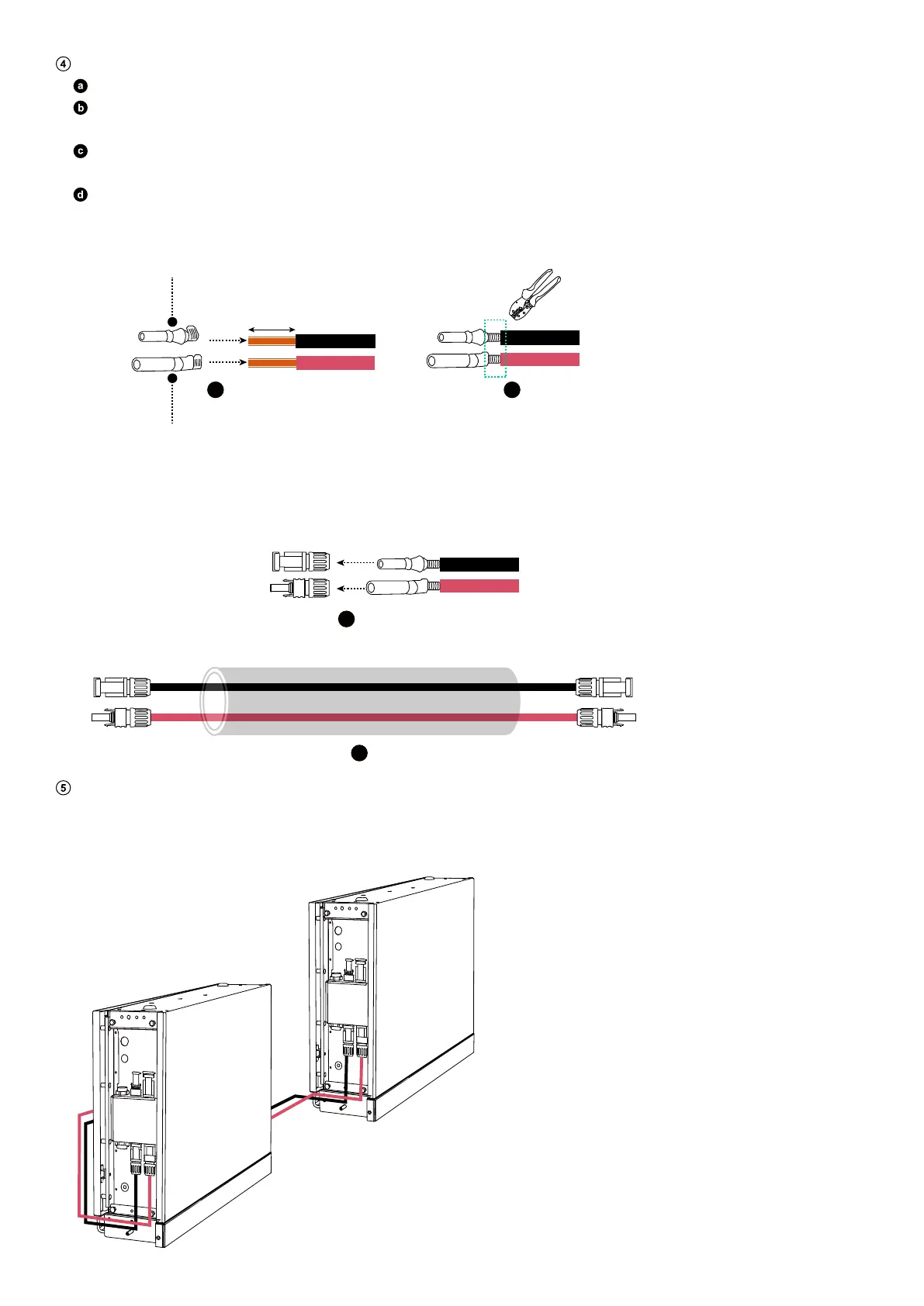
Assemble the positive and negative DC power cables.
Strip the insulation layers from both ends.
Crimp the positive and negative metal terminals (included) onto the corresponding cables. Make sure the terminals are
securely attached and cannot be pulled out.
Insert the positive and negative metal terminals into the corresponding DC power connectors. You should hear a click
when they are properly connected.
Tighten the locking nuts to secure the connection.
Figure: Assemble the DC power cables.
6 mm
a
b
c
d
Negative Metal Terminal
Positive Metal Terminal
Install the positive and negative DC power cables.
On the bottom battery modules in both columns, connect the negative DC power cables (black) to the negative power ports
(BAT-) and the positive DC power cables (red) to the positive power ports (BAT+).
Figure: Install the DC power cables.
BMS
BAT-
BAT+
BMS
BAT-
BAT+
BMS
BAT-
BAT+
BMS
BAT-
BAT+