31
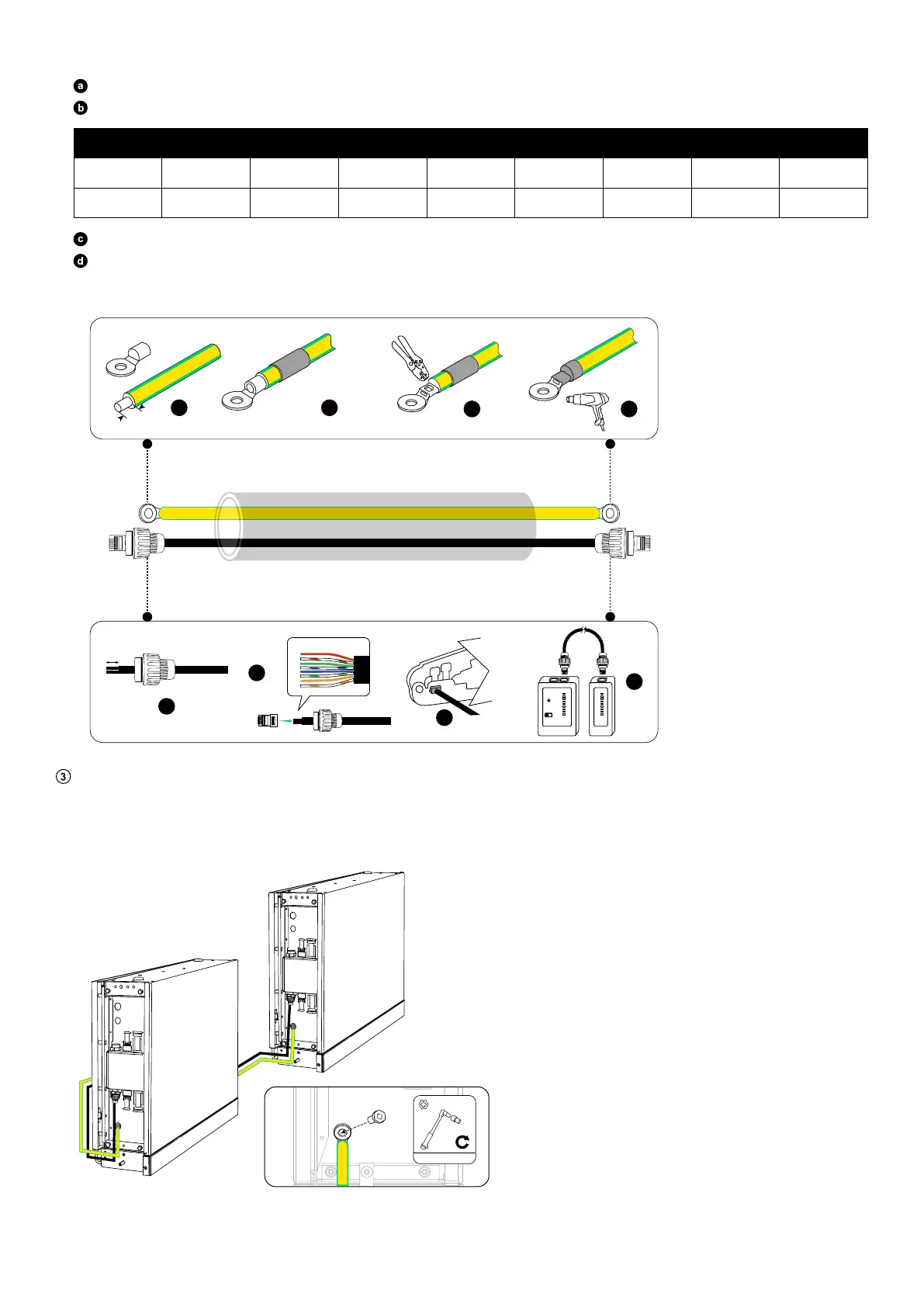
To assemble the RJ45 signal cable:
Insert the signal cable into the RJ45 cable glands, and strip the insulation layers from both ends.
Insert the wires into the RJ45 connectors (included) in the EIA/TIA 568B order.
From Bottom to Top (Clip Faces Away)
Pin 1
2 3 4 5 6 7 8
Wire Color Orange-white Orange Green-white Blue Blue-white Green Brown-white Brown
Crimp the RJ45 connectors using the RJ45 crimping tool.
Use a cable tester to verify proper wiring and continuity.
Figure: Assemble the GND cable and RJ45 signal cable.
8 mm
a
b
c
d
a
b
c
d
25 mm
12345678
6 mm²
1
2
3
4
5
6
7
8
G
1
2
3
4
5
6
7
8
G
Install the GND cable and RJ45 signal cable.
On the bottom battery modules in both columns, connect the GND cable to the ground points and the RJ45 signal cable to the
BMS ports.
Figure: Install the GND cable and RJ45 signal cable.
BMS
BAT-
BAT+
BMS
BAT-
BAT+
BMS
BAT-
BAT+
BMS
BAT-
BAT+
2N·m
M5×14 mm