24
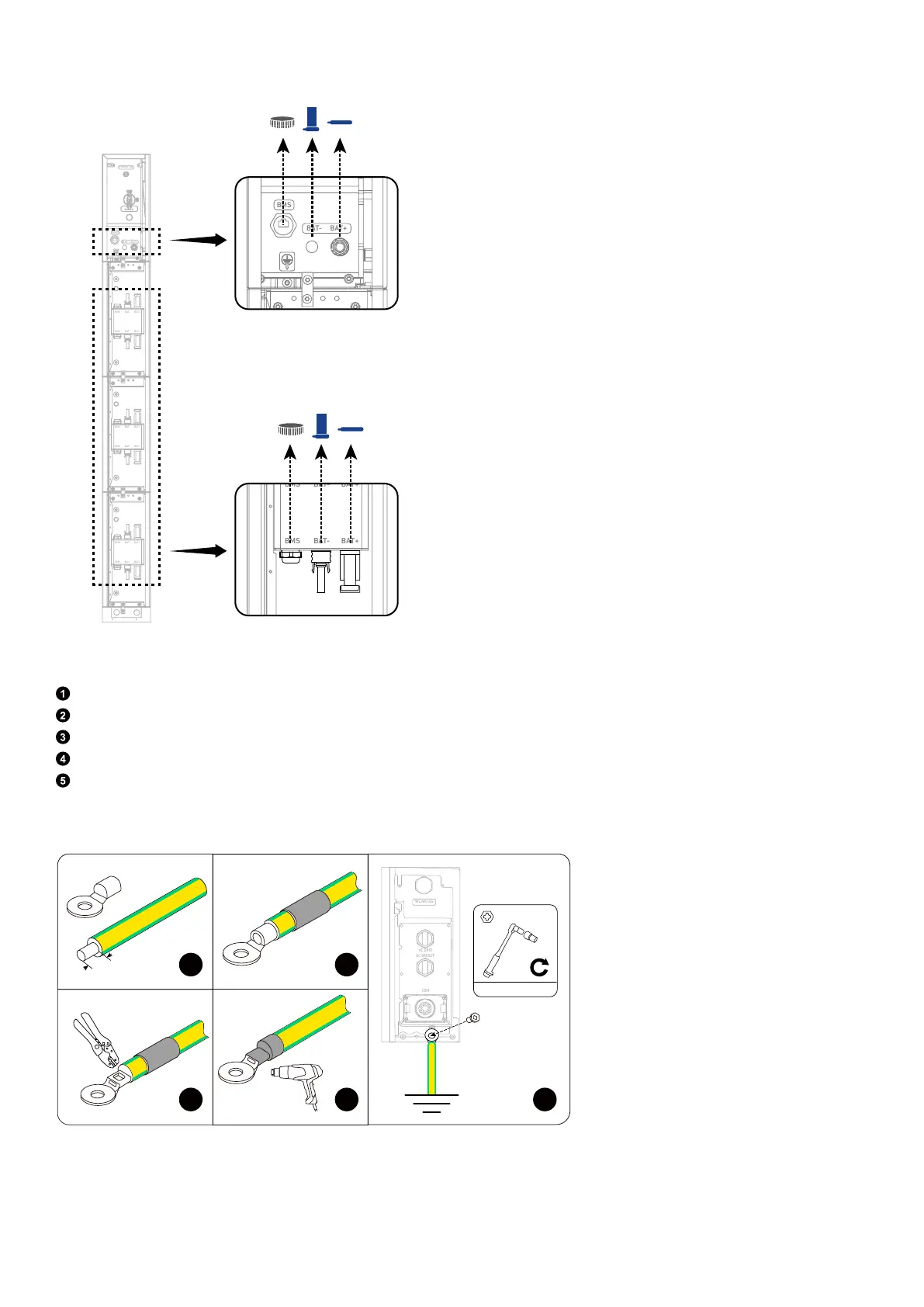
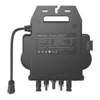
Figure: Remove dustproof plugs from modules.
BAT
SWITCH
BAT
SWITCH
BMS
BAT- BAT+
POWER ON
BMS BAT- BAT+
BMS B AT- BAT+
BMS
BAT-
BAT+
BMS B AT- BAT+
BMS
BAT-
BAT+
BMS
BAT-
BAT+
2. Connect a GND cable from the power module to the external ground point.
Strip the insulation layer of a GND cable (6 mm², yellow/green, not included).
Insert a heat shrink tubing (included) and a ring terminal (included) into the GND cable.
Crimp the ring terminal onto the GND cable.
Wrap the wire crimping area with the heat shrink tubing using a heat gun.
On the right side of the power module, secure the GND cable's ring terminal using the screw (M5×14 mm, included).
Figure: Connect to the external ground point.
1
2
3
WLAN/4G
AC GRID
AC BACKUP
COM
2 N·m
M5×14 mm
4
5
8 mm
6 mm²
3. Connect the GND cables between the modules.
Secure the GND cables (6 mm², yellow/green, included) using the screws (M5×14 mm, included).