Offset Calibration
One of the main contributors to measurement error when measuring the power coming out
of a base station is to assume that the combined loss of the phase stable cable and the at
-
tenuator connected to the output of the instrument is exactly the same as the specified value
of the attenuator. An offset calibration can be used to measure the loss of the attenuator and
cable using a scalar measurement.
The instrument measures the loss of the phase stable cable and the attenuator and uses this
value to subtract the loss for the selected frequency range. The original characterization is
done over the entire frequency range, so there is no need to perform additional calibrations
when the frequency range is changed. The calibration automatically disappears when the in
-
strument is rebooted. It is possible to recall the last calibration and it is also possible to ap
-
ply this offset cal feature to other modes as well (SPA, Interference Analyzer, Channel
Scanner).
Required Equipment
·
Site Master S33xD
·
Test Port Extension Cable, Anritsu 15NNF50 – 1.5C
·
18" (46cm) Test Port Extension Cable, Anritsu 3-806-151
·
10 dB Attenuator, Anritsu 3-1010-119
·
30 dB, 50W, bi-directional, DC–18 GHz, N(m) – N(f), Attenuator, Anritsu 42N50A-30
Procedure
Step 1.
Press the ON/OFF key on the Site Master.
Step 2.
Press the MODE key.
Step 3.
Use the Up/Down arrow key to select the
Power Meter mode and press ENTER.
Step 4.
Press the START CAL (3) key.
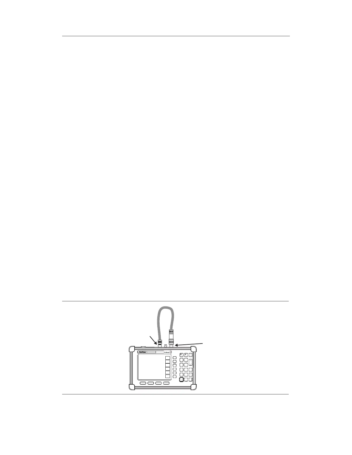
Step 5. Connect the 10 dB Attenuator to the
RF Out connector.
Step 6. Connect the 18" (46cm) Test Port Extension Cable to the
RF In connector and
the 10 dB Attenuator.
6-2
Chapter 6 Power Measurement
HOLD
RUN
START
CAL
AUTO
SCALE
SAVE
SETUP
RECALL
SETUP
LIMIT
MARKER
SAVE
DISPLAY
RECALL
DISPLAY
PRINT
MODE
FREQ/DIST
AMPLITUDE
MEAS/DISP
SYS
ENTER
CLEAR
ESCAPE
ON
OFF
/
1
2
4
5
6
7
8
9
0
3
+
-
.
S332D
18"
able
3-806-151
10 dB Attenuator
3-1010-119
RF Out
RF In
Figure 6-1. Setup for Normalizing the Trace