Do you have a question about the Anrtisu Site Master S331D and is the answer not in the manual?
Provides an overview of the Anritsu Site Master, covering specifications, accessories, and basic operations.
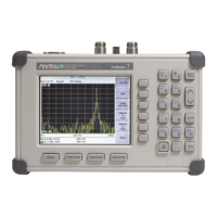
Details the handheld Site Master models S331D and S332D, highlighting features like keypad, display, and power.
Lists essential accessories supplied with the Site Master hardware, including software and cables.
Details various optional features and their part numbers for enhancing Site Master functionality.
Lists compatible printers and accessories available for use with the Site Master S33xD.
Describes Anritsu detectors compatible with the Site Master S33xD when equipped with Option 5.
Lists a comprehensive range of optional accessories for the Site Master, including cables and adapters.
Provides detailed technical specifications for Cable and Antenna Analyzer and Spectrum Analyzer modes.
Outlines recommended procedures for cleaning and inspecting the Site Master and its accessories.
Explains the importance and methods of calibrating the Site Master for accurate measurements.
Describes the InstaCal module for calibrating the Site Master and its operation.
Recommends annual verification of Site Master components and InstaCal module by service centers.
Details precautions to prevent Electrostatic Discharge (ESD) damage to the Site Master.
Defines terms like VNA and SPA used to reference Site Master modes.
Provides an overview of Site Master functions and operations for basic measurements.
Describes the connectors and indicators on the Site Master test panel.
Illustrates key information areas of the S331D and S332D display screens.
Details the Site Master's menu-driven interface, function keys, keypad, and soft keys.
Explains the function of the Mode, Frequency/Distance, Amplitude, and Measure/Display keys.
Lists and describes the functions of the Site Master's front panel keypad controls.
Explains how soft key labels change function based on the current mode selection.
Details the System menu options accessible via the SYS key for various modes.
Provides a listing and description of Self Test and Range Error messages.
Lists possible error messages encountered when using the InstaCal module.
Lists error messages specific to the High Accuracy Power Meter mode with PSN50 sensor.
Lists general error messages that may appear during Site Master operation.
Covers battery charging procedures, remaining life, and important usage guidelines.
Details how to charge the NiMH battery, both within the Site Master and in an optional charger.
Explains how to check the battery indicator and the SYS key for remaining charge.
Provides critical information regarding battery care, charging, storage, and disposal.
Provides an overview of Anritsu Site Master functions for basic measurements.
Step-by-step guide to powering on the Site Master and initiating its startup sequence.
Covers setting frequency, calibration, and trace characteristics for this mode.
Details how to select and configure the Spectrum Analyzer mode for measurements.
Covers common operations like saving/recalling setups/displays, changing units, language, and markers.
Explains how to save and recall instrument configurations for future use.
Provides procedures for saving and recalling trace data and measurement displays.
Describes how to switch measurement units between metric and English.
Explains how to change the display language of the Site Master.
Details how to set and adjust markers for analyzing trace data.
Covers setting single and segmented limit lines for pass/fail measurements.
Explains how to activate an audible beep for limit violations.
Describes how to adjust the display brightness for optimal visibility.
Provides steps for printing the current measurement display to a supported printer.
Demonstrates how to use the soft carrying case for easy access to controls.
Introduces cable and antenna analyzer measurements and line sweeping procedures.
Explains the basics of transmission feed line systems and signal reflection/loss.
Lists essential information needed before performing a line sweep measurement.
Covers common line sweep tests for analyzing transmission feed line performance.
Details how to measure system return loss with the antenna connected.
Explains how to test transmission feed line insertion loss and attenuation.
Describes how to identify fault locations and measure return loss of components.
Details how to verify antenna performance using return loss measurements.
Provides descriptions and procedures for Spectrum Analyzer measurements.
Covers core concepts like resolution bandwidth, video bandwidth, sweep, and attenuator functions.
Explains how resolution bandwidth affects measurement accuracy and signal discernment.
Describes how video filtering affects noise and improves trace visibility.
Discusses sweep time limitations and how the analyzer manages sweep rates.
Explains how attenuation adjusts input signals for optimal dynamic range.
Details the built-in preamplifier for enhanced sensitivity and its operation.
Describes how dynamic attenuation protects the instrument and improves sensitivity.
Covers the interface for connecting frequency converters to extend measurement range.
Explains how to set wireless network standards and channels for accurate measurements.
Details how to perform field strength measurements and correct for antenna factors.
Describes the measurement of occupied bandwidth using percent of power or XdB down methods.
Explains how to measure the output power of a transmitter over a frequency range.
Describes the measurement of adjacent channel leakage power relative to main channel power.
Provides information on analyzing interference using Spectrogram, Signal Strength, RSSI, and Signal ID.
Details how to use the built-in demodulator to identify interfering signals.
Explains the two-step process for measuring carrier level vs. noise/interference.
Introduces power measurement capabilities using spectrum analyzer data.
Details the procedure and equipment required for internal power meter measurements.
Explains offset calibration to accurately measure attenuator and cable loss.
Describes how to switch power readings between dBm and Watts.
Explains how to select and display relative power measurements in dB or %.
Introduces power measurements using broadband RF detectors with Option 5.
Details the procedure, equipment, and settings for power monitor measurements.
Explains how to zero the power monitor for accurate measurements below -20 dBm.
Describes using an attenuator to protect the Site Master from high input power.
Covers how to switch the power display units between dBm and Watts.
Explains how to display relative power readings.
Introduces high accuracy power measurements using Option 19 and PSN50 sensor.
Details the procedure, equipment, and settings for high accuracy power measurements.
Explains zeroing the sensor and entering frequency for calibration factors.
Describes using attenuators and offset features for power measurements.
Covers averaging, max hold, and run hold for stabilizing measurements.
Details how to set measurement limits for pass/fail criteria.
Explains how to display relative power measurements in dB and %.
Provides steps for saving measurement traces with trace names.
Describes transferring saved measurements to a PC using software tools.
Provides an overview of T1 circuits, measurements, and setup procedures.
Explains T1 circuits as backhaul links and their importance in wireless networks.
Defines key metrics for T1 performance testing like AS, ES, SES, and UAS.
Illustrates typical network topologies for T1 circuits between BTS and MSC.
Covers both in-service and out-of-service testing methods for T1 circuits.
Details in-service testing procedures, including Vpp, Carrier, Frame Sync, CRC Errors.
Guides through setting up Bit Error Rate Testing (BERT) for T1 circuits.
Describes out-of-service testing methods like end-to-end and loopback testing.
Explains how to inject errors into the transmit signal for testing.
Details procedures for activating and stopping loopback codes.
Covers testing individual channels (DS0) of the T1 line for performance.
Provides an overview of E1 circuits, measurements, and setup using Site Master S331D.
Explains E1 circuits as backhaul links and their digital signal characteristics.
Defines E1 performance metrics similar to T1, including AS, ES, SES, and UAS.
Illustrates typical network topologies for E1 circuits.
Covers in-service and out-of-service testing methods for E1 circuits.
Details in-service testing for E1 circuits, focusing on Vpp, Carrier, Frame Sync, CRC/E-bits.
Guides through setting up Bit Error Rate Testing (BERT) for E1 circuits.
Details the BERT measurement procedure and display modes.
Describes out-of-service testing for E1 circuits, including procedures and measurements.
Explains how to inject errors into the E1 transmit signal for testing.
Covers testing individual channels (VF) of the E1 line for performance.
Introduces Option 21 for two-port measurements over 25 MHz to 3 GHz.
Explains how to measure amplifiers using Option 21 with external attenuators.
Details the calibration steps for transmission measurements.
Provides step-by-step instructions for performing transmission measurements.
Describes the bias tee feature for providing voltage to RF components.
Introduces the built-in GPS receiver feature (Option 31) for location data.
Provides steps to install the antenna and activate the GPS feature.
Explains how to save measurement traces with GPS coordinates.
Describes how to recall saved displays and view associated GPS data.
Presents information and procedures for Interference Analyzer (Option 25).
Discusses interference problems in wireless networks and Site Master's analysis capabilities.
Describes Spectrogram for identifying intermittent interference using frequency, time, and power.
Explains how to track interfering signals using power at a single frequency with audio indication.
Describes RSSI for observing signal strength at a single frequency over time.
Details how to determine air interface standards and estimated bandwidth of signals.
Presents information and procedures for Channel Scanner (Option 27).
Covers measuring output power of multiple signals and displaying channel amplitude.
Demonstrates a common channel scanner setup procedure.
Introduces CW signal generator mode (Option 28) for receiver sensitivity testing.
Lists the equipment necessary for CW signal generator mode setup.
Details the steps for setting up and using the CW signal generator.
Lists available soft keys for CW Signal Generator mode operations.
Describes the Anritsu Handheld Software Tools program for PC data transfer.
Lists the capabilities of the Handheld Software Tools program.
Specifies the minimum and recommended system requirements for the software.
Provides step-by-step instructions for installing the Handheld Software Tools program.
Guides on setting the PC COM port and transfer baud rate for communication.
Details the installation of null modem serial and USB to serial interface cables.
Explains how to use the software for downloading, uploading, and managing traces.
Describes how to download traces from the instrument to the PC.
Provides steps to capture plots from the instrument display to the PC.
Explains how to upload modified plots from the PC back to the instrument.
Details how to modify plot properties like titles, display mode, scale, and markers.
Covers saving captured plots as metafiles, text files, or to a database.
Explains how to create and manage databases for traces from different sites.
Describes how to set up print formats for multiple plots per page.
Details how to enter antenna factors for field strength measurements.
Explains how to upload antenna factor data from PC to the instrument.
Describes how to download antenna information from the instrument to the PC.
Covers creating and uploading custom cable lists for specific transmission lines.
Allows checking and reviewing the contents of the custom cable list in the Site Master.
Explains how to convert Frequency Domain plots to Distance-to-Fault plots.
Describes using Smith Charts for impedance analysis of transmission lines.
Details the software application for viewing, editing, and creating signal standards files.
Provides a standard listing of common coaxial cables with propagation velocity and attenuation values.
Explains FFT windowing types used for DTF calculation to reduce side lobes.
Illustrates examples of different windowing types and their effects.
Provides a listing of common Spectrum Analyzer signal standards.
| Impedance | 50 ohms |
|---|---|
| VSWR | 1.0 to 65 |
| Power Supply | AC Adapter or battery |
| Display | Color LCD |
| Weight | 2.0 kg (4.4 lbs) |
| Distance-to-Fault (DTF) | Yes |
| GPS | Optional |
| Operating Temperature | -10°C to +55°C |
| Storage Temperature | -40°C to +75°C |