11 | LUME20 – Manual | AntecControls.com
Once the installation locations have been selected, the sensor plates can be mounted using the following steps.
Prior to mounting the sensor plates, cut the ninety-six inches (96 in.,
2.44 m) clear tubing to the required length for the distance from each
plate to the sensor. E.g., if the plate for the isolation room is five feet
(5 ft, 1.52 m) from the SDPT and the plate for the corridor is three feet
(3 ft, 0.91 m), cut the provided tubing into one five-foot (5 ft, 1.52 m)
and one three-foot (3 ft, 0.91 m) length.
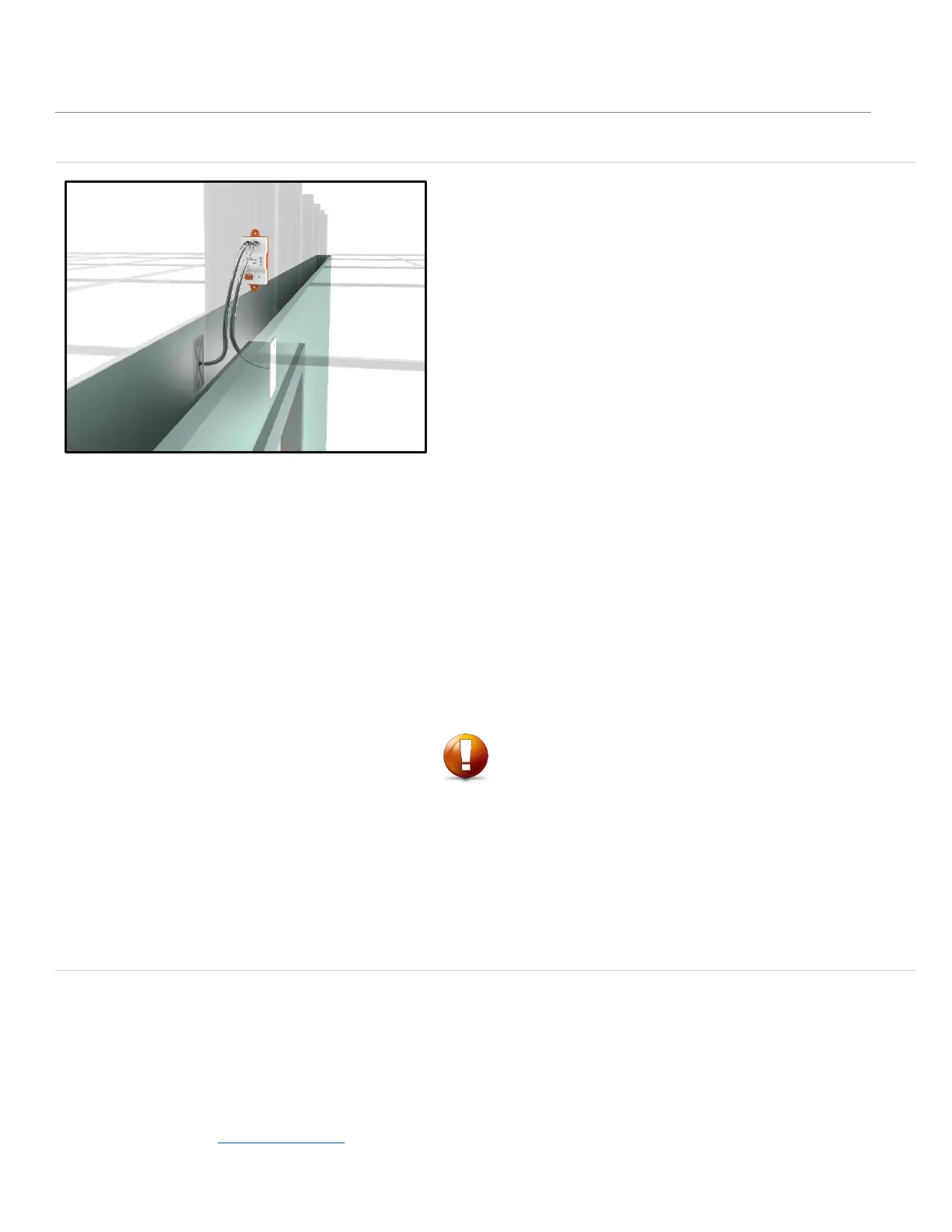
To mount the ABS sensor plate directly to the wall:
1.
Cut a one-inch (1 in., 25.4 mm) hole for the tubing to pass
through.
2.
Use the sensor plate to mark the holes for the anchors
(anchors require 3/16 in., 4.8 mm drill). Drill hole and install
the provided anchors.
3.
Push the clear tubing onto the pickup on the back of the
sensor plate.
4.
Run the tubing through the one-inch (1 in., 25.4 mm) hole in
the wall and mount the sensor plate to the surface using the
provided screws.
5.
Connect the tubing to the SDPT.
a.
Monitored space to high pressure port.
b.
Reference space to low pressure port.
To mount the stainless steel sensor plate directly to a single gang
electrical box:
1.
Knockout a hole for the tubing to pass through.
2.
Push the clear tubing onto the pickup on the back of the
sensor plate.
3.
Connect the tubing to the SDPT.
a.
Monitored space to high pressure port.
b.
Reference space to low pressure port.
CAUTION
Make note if the tubing is reversed when installed. If the corridor is connected to
the high pressure port on the SDPT, the reading can be reversed during setup.
Do not extend the pressure tubing past the provided length of ninety-six inches (96
in., 2.44 mm). Extending the tubing past this length can result in degradation
of the pressure reading.
Do not connect tubing from the SPDT to any other pressure measurement devices
or other SDPT sensors.
Do not tee off the tubing to connect to any additional devices.