>
5
m
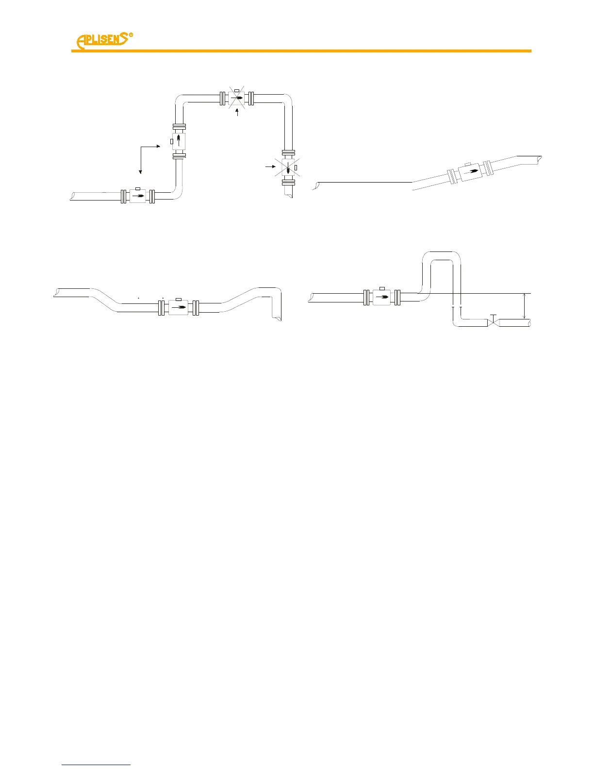
If vertical pipeline longer than 5m
downstream the sensor, install
deaerating valve (underpressure)
7.2. Recommended assembly method for the sensor
Figure 6. Recommended assembly method for the sensor
To avoid metrological errors caused by air bubbles or liner damage, consider the following
recommendations:
- During the assembly set the sensor properly, tighten the screws of the flanges, placed
opposite each other, evenly one after another.
- The properly selected seal of the flanges ensures better effect than the excessive
compressive force which may deform the flanges.
- The sensor should be mounted on the pipe to guarantee the axis of the measuring
electrodes of the sensor to be always horizontal.
- Teflon liner requires particular attention during servicing and assembly. During
the installation process the excessive negative pressure in the pipeline should be
avoided. The stub-ups of the liner to the external surfaces of the flanges on both sides
of the sensor must not be damaged. The sensors are supplied by the manufacturer
containing special covers, which prevent deformation of the Teflon liner. The covers
must be removed directly before the assembly, right before the insertion between the
counter flanges.
- Seal – the part of the liner extended to the external surfaces of flanges fails to function
as a seal, hence it must be placed between the flanges of the sensor and the pipeline.
The seal protruding inside the pipe generates the flow turbulence and reduces
the accuracy of measurements.
 Loading...