EasyManuals Logo

Aplisens PEM-1000 User Manual

Aplisens PEM-1000
40 pages
To Next Page IconTo Next Page
To Previous Page IconTo Previous Page
Page #21 background imageLoading...
Page #21 background image
IO.PEM-1000(ENG)
02.A.003 21
8.1. Electrical connection of the flow meter
Access to electrical terminals of the flow meter is obtained when the side cover of
the housing of the converter gets unscrewed.
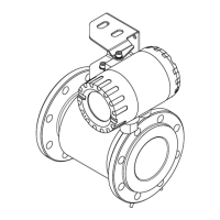
The following figure and the table show the distribution and purpose of individual terminals.
Terminal
no.
Description
Power supply
1
mains power
(-)
low-voltage DC
power supply
(optional)
2
(+)
Binary output 1
3
any polarity
galvanically isolated
passive
4
Pulse/frequency output
5
passive
any polarity, galvanically isolated
6
Analog current output
4 ÷ 20 Ma
7
(+)
active / passive
(default active)
8
(-)
Communication
9
RS 485 A
galvanically isolated
ground should be connected
10
RS 485 B
11
RS 485
ground/screen
Passive binary input
12
any polarity
galvanically isolated
13
Binary output 2
14
any polarity
galvanically isolated
passive
15
Figure 10. Marking and descriptions of connecting PINs of the flowmeter PEM-1000.

Table of Contents

Questions and Answers:

Question and Answer IconNeed help?

Do you have a question about the Aplisens PEM-1000 and is the answer not in the manual?

Aplisens PEM-1000 Specifications

General IconGeneral
BrandAplisens
ModelPEM-1000
CategoryMeasuring Instruments
LanguageEnglish

Related product manuals