4 02.A.003
10.5.4. Basic principles for selection of the DN size (acc. to DIN) of the flowmeter for the
nominal flow Qn .............................................................................................................. 35
10.6. Allowable ambient and operation parameters ........................................................... 36
10.6.1. Electromagnetic compatibility, immunity ............................................................. 37
10.6.2. Electromagnetic compatibility, emissions ........................................................... 37
10.6.3. Mechanical resistance ........................................................................................ 37
10.6.4. Insulation resistance ........................................................................................... 37
10.6.5. Insulation resistance ........................................................................................... 37
10.6.6. Ingress protection of the enclosure .................................................................... 37
11. INSPECTIONS. CLEANING. SPARE PARTS ........................................... 38
11.1. Periodic inspections .................................................................................................. 38
11.2. Non-periodic inspections ........................................................................................... 38
11.3. Cleaning/washing. ..................................................................................................... 38
12. SCRAPPING, DISPOSAL ......................................................................... 38
13. ADDITIONAL INFORMATION ................................................................... 38
13.1. Additional information ................................................................................................ 38
14. REVISION LOG ......................................................................................... 38
LIST OF FIGURES
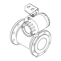
Figure 1. The flow meter PEM-1000ALW. The compact version ............................................. 9
Figure 2. The flow meter PEM-1000NW. The remote version. .............................................. 10
Figure 3. The flow meter sensor. Overall dimensions ........................................................... 11
Figure 4. Converter of the flow meter PEM-1000 with the mounting bracket. Overall
dimensions ............................................................................................................................. 14
Figure 5. Mounting bracket. Overall dimensions ................................................................... 14
Figure 6. Recommended assembly method for the sensor ................................................... 17
Figure 7. Assembly of the flow meter PEM-1000ALW – examples. ...................................... 18
Figure 8. Assembly of the flow meter PEM-1000NW – examples ......................................... 19
Figure 9 Stub-ups of electrical cables from the converter of the flow meter PEM-1000. ....... 20
Figure 10. Marking and descriptions of connecting PINs of the flowmeter PEM-1000. ......... 21
Figure 11. Preparation of the power cable ............................................................................ 22
Figure 12 Marking of the stub-ups of the sensor cable conductors ....................................... 24
Figure 13 Connecting PINs of the sensor cable plug ............................................................ 24
Figure 14 Manner of connection of the protective earth for the flow meter. ........................... 25
Figure 15 Manner of driving the line of the earthing functional in the PEM-1000 flow meter. 26
Figure 16 Manner of connection of the earthing functional for the converter housing. .......... 27
Figure 17 Manner of connection of the earthing functional for the sensor housing. .............. 27
 Loading...