J:\Etude-3d\Aquaset\0-DOSSIER TECHNIQUES\1-sw-plaisance\ESW\00-ESW 0707\09- Manuels Utilisateur\DOC UTILISATEUR ESW FRUKES 2009-10-C.doc VERSION 2009-10-C FR/UK/ES Page 21/58
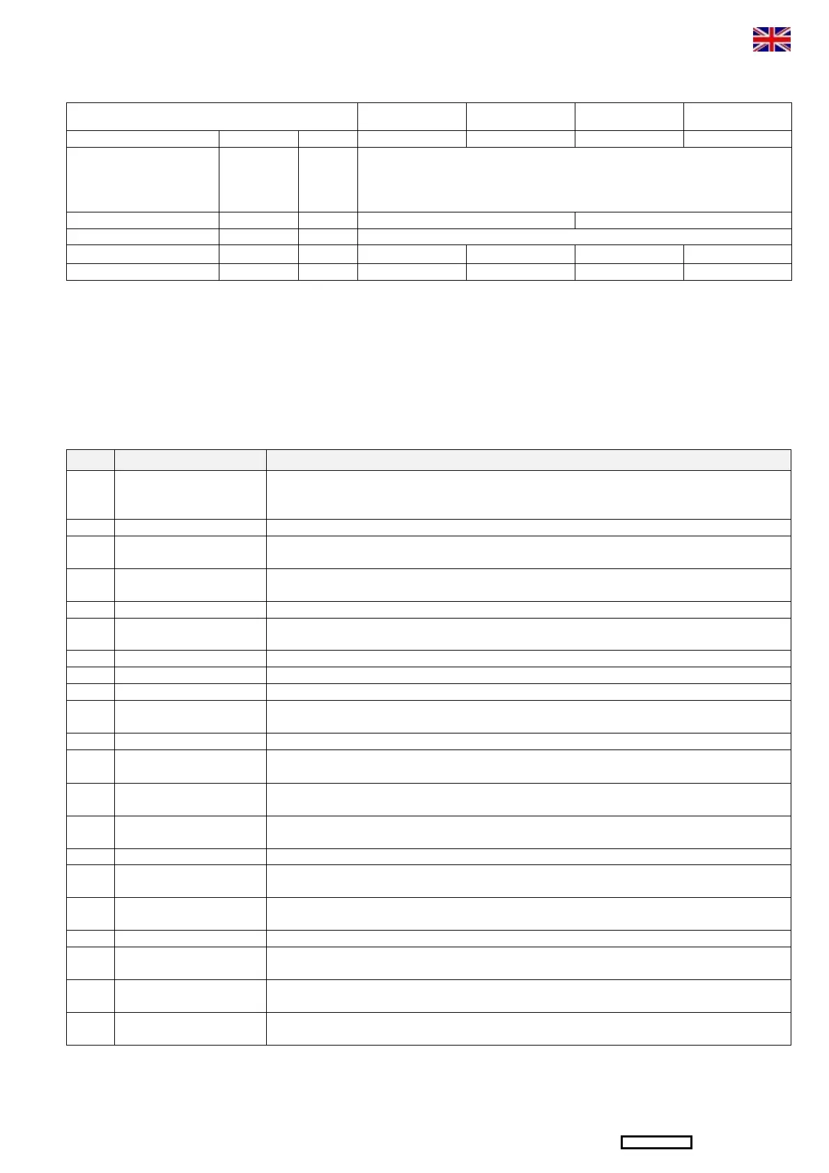
2 – CHARACTERISTICS
TYPE ESW 301 ESW 601 ESW 302 ESW 602
Dry mass Kg 48 56 48 56
Pipes
Feeding
Reject
Production
A1 / A2 / B
C / D / E
F
mm
mm
mm
19 X 27
19 X 27
8 x 13
Voltage Vcc 12 24
Pressure (1) bar 40 to 60 (depends version)
Elec. Consumption A
12 29 6 13
Std. Capacity (2) l/h 30 60 30 60
(1) The pressure is automatically adjusted, depending on operating conditions (water salinity and temperature).
(2) The nominal capacity is given for a new unit, nominal membranes performances, operating in standard seawater TDS 35000ppm (35g/l) and temperature
25°C. The capacity can vary from +/-15%, according to allowances given by the manufacturers of the membranes.
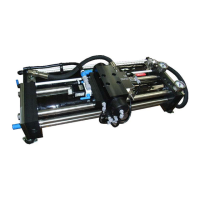
3 – DESCRIPTION
3.1 – WATER SYSTEM (SEE FIG.2 AND FIG.3 NEXT PAGE)
In the basic version, desalinator ESW is made up of the following elements:
REP. DESCRIPTION FUNCTION
EdM Hull fitting
Always immersed, it ensures continuous seawater feeding of the unit. Not included in the supplies.
Not take the water on the driving cooling circuit. Place the hull valve (V0) in most farther of the hull
valve ( R ).
V0 Hull valve
Situated near the hull fitting, insures shutting of seawater feeding. Not included in the supplies.
A1/
A2/B
Feeding pipes Ensures feeding of the unit through the filter (4).
1 Inlet valve Manual 3-way valve ensuring feeding of the unit, either with seawater in normal operating, or with the
water or chemical solution contained in a bucket during cleaning or preservation of the membrane.
2 Sea Strainer Contains an element ensuring seawater filtering to protect the booster pump (LP).
3 Low Pressure Pump Driven by an electric motor, it raises seawater pressure to the required value up to 6 / 9bar. Must be
installed 200mm below the water line.
4 5 µ filter Contains an element ensuring seawater filtering at 5µ (essential before the membrane).
5 LP Pressure Gauge Indicates the LP pressure.
6 Hydraulic amplifier Increase seawater pressure to produce fresh water through the R/O membrane.
7 Air bleed valve To bleed the system at the first start-up, or after replacement of the filters. Allows operation of the unit
at low pressure when opened for cleaning or preservation operations.
9 HP Pressure Gauge Indicates the HP pressure.
10 R/O module Made up of pressure-resistant vessels, containing the membrane in which the desalination of
seawater is carried out.
11 Cleaning valve By opening this valve, the valve (1) itself being turned to rinsing position, the unit can be operated in
closed circuit on a bucket containing cleaning solution.
14 Valve 3-way Electromagnetic 3-way valve controlled by the salinity cell. It automatically directs the produced water
towards the tanks if the salinity is correct, or towards discharge to the sea, if it isn’t.
15 Actived carbon filter For dechloration of fresh water of rinsing to preserve the membrane.
17 Salinity cell Continuously measures the salinity of the produced water, and controls the valve (14) according to
this measure.
18 Electrovalve of rinsing Insure automatic rinsing of the desalinator by taking fresh water from the network of water on the boat
in load.
C Reject piping Collects the concentrated brine produced by the membrane for discharge to the sea.
R Hull fitting
Situated above the water line, ensures brine discharge to the sea. Not included in the supplies.
(avoid installing the reject in front of the entry seawater).
E Rinsing pipes Ensure feeding of the unit with fresh water and chemical solutions stored in a bucket or a holding
tank, during membrane cleaning operations.
D Cleaning pipes Direct the unit discharge towards the auxiliary bucket (after tilt the valve 11), thus ensuring cleaning of
the membranes in a closed loop.
(See 3.2 – Flow chart and 3.3p22 – Installation on board)
 Loading...